 [Table of Contents]
People old and young enjoy waxing nostalgic about and learning some of the
history of early electronics. Popular Electronics was published from October 1954 through April 1985. All copyrights (if any) are
hereby acknowledged.
See
Popular Electronics articles
on aircraft modeling. See all articles from
Popular Electronics.
|
Early "servos" were nothing more than the electromechanical
equivalents of rubber band-powered escapement. Rather than energizing a solenoid that would allow the
rubber band to turn the control arm, the pulse signal from the receiver would set a motor in motion,
and then limit switches would stop it once the predetermined position was reached. They had a number
of advantages over rubber-powered escapements in that the power delivered to the control surface was
not diminished with every actuation (except from some negligible energy drain from the batteries), they
were able to deliver a lot more power, and they took up less real estate inside the fuselage. It was
a first step toward today's proportional servos.
See complete list of Popular
Electronics articles on aircraft modeling.
 Compound Escapements & Servos Compound Escapements & Servos
by E. L. Safford, Jr.The more advanced the radio-control hobbyist becomes, the more functions seeks
to control on his model airplane, boat, or racing car. To effect multiple control operations, complicated
escapements have been designed. Some of these will be explained in this article.
 The
escapement illustrated in Fig. 1 was created in order to obtain direct control over two physical functions
using a single-channel type receiver. In model aircraft for example, it is used to control both rudder
and elevator. One particular advantage of this unit is that it only deflects the control surfaces in
the "on" signal positions and returns both to neutral in the "off" signal positions. This is a safety
feature of considerable merit. The
escapement illustrated in Fig. 1 was created in order to obtain direct control over two physical functions
using a single-channel type receiver. In model aircraft for example, it is used to control both rudder
and elevator. One particular advantage of this unit is that it only deflects the control surfaces in
the "on" signal positions and returns both to neutral in the "off" signal positions. This is a safety
feature of considerable merit.
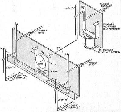
Notice that this escapement consists of two two-finger escapement arms and catch- points located
on a single plate with a cam mounted between them. The cam has a pin extension C. In the drawing, a
spring is shown holding catch-points 2 and 3 firmly against the cam wheel causing 1 and 4 to rise up
and intercept fingers A and D. This is the starting neutral position.
 Fiq. 1. A type 2 compound escapement in which one standard two-finger
escapement is used to actuate two separate control loops via a cam.
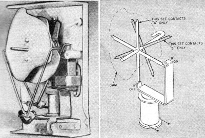
 Fig. 2. (left) Back view of an ECCO compound escapement which
uses two four-finger units and two cam wheels to actuate two "Y" yokes, each with its own shaft. This
allows two control functions.
Fig. 3. (right) Simplified drawing of the ECCO compound escapement showing how the four-finger units
operate separately with a single solenoid.
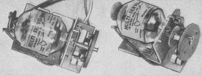
 Fiq. 4. Top and side views of a typical servo unit for radio
control. Motor is about 1" wide.
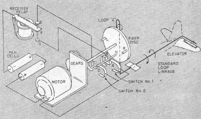
 Fiq. 5. Physical drawing indicating how a servo may be used
in a radio-control model airplane for proportional control of the elevator. It can be used also for
the rudder.
If now, a signal is sent causing the standard two-finger escapement to move finger F to position 6,
the cam is caused to rotate 90 degrees counterclockwise pushing catch-point 2 forward causing catch-point
1 to move down, releasing A. As A rotates clockwise, finger B is intercepted by catch-point 2 and held.
Loop N is deflected to the left.
Now assume that the signal ceases. The arm on the standard escapement rotates another 90 degrees
until G is intercepted by 5. Through loop L, the cam is rotated another 90 degrees, allowing catch-point
2 be pulled back by the spring and forcing 1 up to intercept B. Loop N is again at neutral.
Another "on" signal causes the cam to push catch-point 3 forward to intercept E, deflecting loop
M to the right. An "off" signal sends the cam back to the starting point, leaving E held firmly by 4
and loop M again at neutral.
Tracing the action through a second evolution of the cam will show that first loop N is deflected
to the right, then brought to neutral, then loop M is deflected to the left, and brought back to neutral.
It has taken two complete revolutions of the cam to go through the complete cycle of operation for both
loops.
Although it is necessary to go through the complete cycle in order to effect any one desired control
and return to the original starting position, this is not necessarily a disadvantage if the operation
is done fast enough. Other surfaces may move, but will not be held in a deflected position long enough
to affect the steering.
Another multiple escapement, this one sold by ECCO, is illustrated in Fig. 2. The back cover has
been removed in order to reveal the special working parts. It, too, allows control over two physical
functions. It is a single, self-contained unit requiring but a single rubber band for power.
The movement of the two output shafts is obtained through the use of the two specially shaped cams,
the two "Y" yokes, and two sets of "four-fingers" which engage the armature catch-points. The two catch-points
are offset from each other so that only one set of fingers contacts the "on" catch-point, the second
set contacting the "off." This is illustrated in Fig. 3.
If the outer cam of Fig. 2 were to rotate 90 degrees clockwise because of rotation of the fingers,
the protrusion of the cam would force the left half of the "Y" yoke to the left. At the same time the
indented portion of the cam is moved opposite the right half of the yoke, allowing motion to the left.
Another quarter revolution returns the "Y" to neutral. The third quarter revolution moves the "Y" right,
and the final 90 degrees returns the "Y" to neutral and the cam to its original starting position. This
action has taken place in four steps.
Since there are two sets of "four-fingers," mounted as illustrated in Fig. 3, there are actually
eight catch positions instead of just four. Thus, with the proper placement of the two cams, the signal
sequence is as shown in Table 1 .
Notice that the deflection of the yokes occur only in the "on" signal positions. This again is a
fail-safe feature.
Servos
First, to remove any mystery that might be connected with the word servo, this word comes from the
Latin and means slave. Since slaves were once used to do the hard physical work, the word in modern
electronic parlance has come to mean the unit which furnishes physical power in a control system; in
particular, motors.
The De Bolt 2PN "Multi-Servo" shown in Fig. 4 is an electric motor with associated reduction gears,
switches, and anti-coast device. It can be used in the same manner that the standard two-finger escapement
is used to move control surfaces. The designation 2PN indicates its operation. This stands for "two
positions-one neutral."
Examination of Fig. 4 will reveal the small brass terminal on the face of the fiber disc to which
the linkage to the control surface is fastened. Notice also the two brass switches mounted below and
behind the output disc, and the small fiber pins on the inside of the fiber disc which open the switches
at the proper time.
Comparing this unit to escapements highlights the following:
1. No rubber bands are required.
2. Servos are small and lightweight (2 ounces).
3. They have fast response and are reliable.
4. They require conservative battery power (2 pen cells or their equivalent).
5. They are failure-safe in case if receiver failure.
6 They consume no power in any control or neutral position.
7. They are rugged and compact.
8. They have a simple and definite control sequence. The sequence is easy to remember and transmit
using a standard pushbutton, it is "off" for neutral; "on" for left; and "on-off-on" for right.
Fig. 5 shows a typical wiring setup for a servo. Notice the fiber disc and the fiber shafts labeled
N, R, and L. In the position shown, neutral, shaft N is depressing switch 2, opening its connection
to D. The shaft does not open switch 1 since this switch is located lower than switch 2 and shaft N
is placed nearer the center of the disc than L or R.
Let's trace through a signal sequence to see the operation. First an "on" signal is transmitted.
The armature of the receiver relay F is pulled down to make contact with G. This lets power flow from
the battery through the relay to B of switch 1. B is making contact with A, so the power goes through
this switch to one side of the motor. The second motor lead is permanently fastened to the battery,
so the motor runs, turning the fiber disc in a clockwise direction until shaft R opens switch 1, breaking
the circuit and causing the motor to stop. As the fiber disc rotates, it moves loop Z to the right,
giving down elevator. As long as the signal is sent, the loop will remain deflected, but since the circuit
to the motor is open, the servo consumes no power.
 Now the signal ceases. The receiver relay armature moves from G
to E. Power now flows through switch 2 to the motor, causing it to run again. It runs until shaft N
opens switch 2, opening the circuit. Loop Z is back to neutral. Now the signal ceases. The receiver relay armature moves from G
to E. Power now flows through switch 2 to the motor, causing it to run again. It runs until shaft N
opens switch 2, opening the circuit. Loop Z is back to neutral.
To get up elevator, the sequence is "on-off-on," holding the second "on" as long as this control
position is desired. It is important that the sequence be sent at a medium rate and not too fast. The
first "on" causes the motor to run as before, but in-stead of stopping, the "off" signal comes and routes
power through switch 2 while switch 1 is being opened up by the shaft R. The second "on" comes as L
approaches switch 1, and since this signal is held, the motor stops running when L opens switch 1. The
loop Z will now be right, giving up elevator. When the signal stops, the motor again returns the loop
to neutral. While the illustrated action has concerned the elevator, it should be mentioned that it
works as well for rudders or steering wheels.
END
Posted July 25, 2011
Vintage Popular Electronics Magazine
Articles-
Simple Dual Proportional R/C System - September 1956
-
An Experiment with Gravity, January 1970
- R/C Notes, January
1956
-
R/C
Triplex: Three Controls on One Channel, November 1956
- R/C Reliability,
March 1955 Popular Electronics
-
Robot Helicopter, November 1956
-
Model Boat for the 27 mc. Citizens Band , March 1953 Radio & Television
News
- Adjusting
the Power - R/C Plane, January 1955
- Rejuvenate
R/C Batteries, July 1955
- 3 and 4 Finger
R/C Escapements, January 1955
- Radio Control
of Models, October 1954
- The R/C Cloud,
February 1960
- Radio
Control Installations, February 1955
-
Compound
Escapements & Servos, February 1955
- Flying the R/C
Plane, December 1954
- The Lorenz
Transmitter, December 1954
|


