|
May 1962 Radio-Electronics
 [Table
of Contents] [Table
of Contents]
Wax nostalgic about and learn from the history of early electronics.
See articles from
Radio-Electronics, published 1930-1988. All copyrights hereby
acknowledged. |
We take for granted today that we are able to legally use radio control systems
without obtaining an operator's license, but that has only been the case since
the late 1970s. Prior to that, a Citizens Radio Station License needed to be
procured from the Federal Communications Commission (FCC). No examination was
required, but a fee was charged. I think mine cost something like $5. FCC
Part 15 rules permitted license-free operation in designated frequency bands
then as it does now, with a limit on maximum power output for
both intentional and unintentional radiation. Many of the commercial radio
control systems from companies like Kraft, Orbit, Ace, Logictrol, Futaba, OS
(World Engines), and other put out around one watt of power, in order to help
assure that there was plenty of range to prevent "flyaway" airplanes. At the
same time R/C systems operating in the 27 MHz band became license-free, so did
citizens Band (CB) radio, which shared the band (with primary rights), so that
really made operation risky for flyers. Most hobbyists soon made to the
privileged 72 MHz band, where we only needed to worry about being "stepped on"
by some fool in the pit area turning on his transmitter without making sure the
frequency was clear. Now, with R/C systems operating in the 2.4 GHz ISM band
with spread spectrum modulation, there are no worries.
License-Free Radio Control
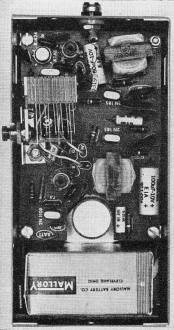
Inside the Heathkit GW-30. This unit is about to be modified
for license-free R/C use.
Check the FCC regulations; you'll find you can operate without a license
By Donald L. Stoner
Although it is not generally known, you can operate a radio-controlled model
without a license. Anyone who has taken the time to read paragraph 15.205 of "Part
15 - Incidental and Restricted Radiation Devices" of the Federal Communications
Commission Rules and Regulations will discover that a low-power communications device
may operate between 26.97 and 27.27 mc (27.12 mc ±150 kc) provided it complies
with the following requirements:
• The carrier of the device shall be maintained within the band 26.97 to
27.27 mc.
• All emissions, including modulation products below 26.97 or above 27.27
mc, shall be suppressed 20 db or more below the unmodulated carrier output.
• The power input to the final radio stage (exclusive of filament or heater
power) shall not exceed 100 milliwatts.
• The antenna shall consist of a single element that does not exceed 5 feet
in length.
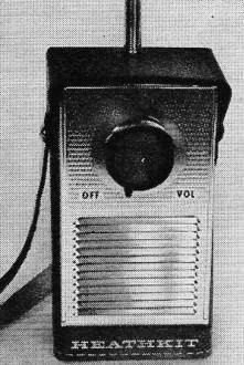
The GW-30 handheld CB transceiver.
The intended use is not specified and thus Part 15 radio-control equipment may
be considered permissible. Note also that no specific channel assignments are made
(subpart a) and that any frequency between the limits specified can be used. The
carrier frequency could be "wedged" between two Citizens band channels where interference
is at a minimum.
There is one other point which should be mentioned in connection with the rules
and regulations: Part 15.208 (d) states, "The certificate may be executed by a technician
skilled in making and interpreting the measurements that are required to assure
compliance with the requirements of this part." Thus, if you are technically qualified
to make the required measurements (second harmonic, modulation bandwidth, power
input, etc.), you can build a transmitter or modify a commercial unit. No second-class
radio-telephone license is required. However, if equipment is found to be operating
improperly or in violation of regulations, then the certifying person may be called
for a hearing before FCC examiners. If he is found to be unskilled in making and
interpreting measurements required for certification, then he may be prosecuted.
Although the power input of equipment used under Part 15 is limited to 100 milliwatts
(0.1 watt), this is adequate for up to 1-mile range. Radio-control transmitters
are usually operated with a continuous carrier. Only the tone is pulsed to actuate
a receiver escapement or relay. This system is more reliable since the carrier tends
to override interfering stations. Experience has shown that battery-consuming high-power
transmitters are not required since the model seldom goes more than 1/2 mile away.
Modern transistor receivers are more selective and sensitive than their vacuum-tube
predecessors. Completely transistorized receiver and transmitter systems are not
only practical but are commercially available (Wen-Mac, etc.).
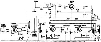
Fig. 1 - Circuit of the Heathkit GW-30.
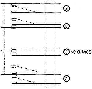
Fig. 2 - Detailed view of the modified switch.
A Part 15 R/C Transmitter
To prove that a low-power transmitter could be used for radio control a Heathkit
GW-30 Citizens-band transceiver was modified to work in conjunction with a transistor
radio-control receiver, an F & M Electronics Pioneer model. The circuit of the
GW-30 is shown in Fig. 1.
The modifications involve disabling the GW-30 receiver and inserting feedback
in the modulator section to generate a tone. The transmitting frequency of the GW-30
need not be changed.
Here's how to modify the GW-30.
Take the unit out of its leather case and remove the back panel. Lift the printed-circuit
board from the case after removing the three screws that secure the chassis. Familiarize
yourself with the location of the pushbutton switch contacts (Fig. 2 and the photograph).
This switch is modified so the transmitter carrier comes on when the volume control-switch
is turned on. Depressing the button, in the modified GW-30, then produces a tone
rather than turning on the carrier.
It is easier to bend the switch contacts than to rewire the switch to do this.
They may be straightened later if a return to the original operation is desired.
Note the dotted lines in Fig. 2. Bend the fixed contact on section B up so it touches
the moving contact. This completes the emitter circuit of transmitter transistor
V4. Next bend the fixed contact on section C up. This breaks the primary circuit
of T1 and disables the receiver. Do not modify section D. Finally, on section A,
bend the upper fixed contact up to clear it from the moving contact. Bend the lower
fixed contact of section A so that it touches the moving contact at ail times. This
connects the antenna to the transmitter section. Finally, the modulator is made
to oscillate by introducing feedback.
This can be done by reconnecting section D of the switch to tie the modulator
output to the input. Locate the wires which connect section D to the speaker and
T2. Reverse these two wires by "swapping" the connections from section D of the
switch on the circuit board. Thus you can see that when they are connected in this
manner, depressing the pushbutton connects the speaker winding on T1 to the speaker
winding on T2. When this is done, the audio stages break into oscillation and tone-modulate
the transmitter. This completes the changes to the unit and it can now be reassembled.
Although the modifications sound complicated, it actually takes more time to
tell how to make them than to do the job.
To test the conversion, check the transmitter by energizing a radio-control receiver
in a model on the ground. It should actuate the control surface reliably over a
distance of 1,000 feet and more when the model is held aloft. In operation, the
transmitter is energized, before launching the model, by turning on the volume control.
As soon as the model is 50 to 100 feet from the transmitter and has enough elevation,
the control button can be depressed. The exact sequence of operation will depend
on the escapement used.
|