|
As with most things these
days related to model airplane (and everything else) components, extensive
research into materials, structure, and functionality have been thoroughly
researched and engineered to the point where the modeler has little more to do
that install parts into his craft. Parameters have been thoroughly analyzed
using computers over a wide range of input stimuli to determine the optimal
configuration. Jet engines, brushless motors, retractable landing gear, lighting
systems, radio systems, cockpit details, pilots, even wheels and hinges, can all
be purchased for a relative pittance with full confidence that they will meet
expectations. Not so back in 1956 when this article appeared in Air Trails
magazine. The effort dedicated by author Wayne Schindler to design and conduct
an experiment to determine the optimal dimensions and shapes for a ducted fan
propulsion system is nothing short of academic. His efforts produced a list (Schindler's list, you
might say)
of design parameters to consider when building a ducted fan-powered model
airplane. The net result in Mr. Schindler's case was an amazing 325% thrust
improvement over his initial configuration.
There's Nothing Mysterious About Ducted-Fan Models!
 By Wayne A. Schindler By Wayne A. Schindler
After studying the various articles on ducted-fan propulsion and finding little
useful information for converting to individual use, we decided to set up a series
of experiments that would show us exactly how to go about designing a practical
system.
The first step was to decide on the general type of ducted-fan propulsion to
use - the wing root intake system or the straight-through system. Since most present-day
jet aircraft have wing root intakes, we decided to develop a system that utilized
these intakes. This would enable us to keep the nose of the model free for radio
control equipment on a larger model. This system could also be used for U-control
scale or Navy Carrier Event models or Half-A free-flight scale craft.
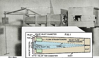
Definitions of the terms to be used are necessary to eliminate any misunderstandings
(Fig. 1).
Duct - the thrust tube used to concentrate and direct the flow of air after it
leaves the blades of the fan.
Exit - the duct exit out of which flows the accelerated air. Inlet-the entrance
of the duct tube into which the air is forced by the fan.
Intake - the exterior air intake areas which feed the air into the fan.
The first step in designing the test unit was to determine the most efficient
exit-to-inlet ratio of the duct. Four ducts were built having a constant inlet diameter,
and a varying exit diameter for each:
One with a 2 1/2" exit and a 4" inlet, ratio 0.67 to 1
One with a 3" exit and a 4" inlet, ratio 0.75 to 1
One with a 3 1/2" exit and a 4" inlet, ratio 0.87 to 1
One with a 4" exit and a 4" inlet, ratio 1 to 1
 Using a 3 7/8" diameter, twelve-bladed fan turning at 8,500 rpm, the thrust output
of each tube was measured and it was found that the 0.87 to 1 ratio produced a 15%
increase in thrust over the others. Using a 3 7/8" diameter, twelve-bladed fan turning at 8,500 rpm, the thrust output
of each tube was measured and it was found that the 0.87 to 1 ratio produced a 15%
increase in thrust over the others.
The test stand shown in Fig. 2 was built using this ratio. It included a removable
intake hood with variable intake slots at the sides and front and a balance system
to record the variations in thrust. A damper system had to be added to the balance
unit to reduce transmitted vibrations so accurate readings could be taken. This
is the arm dropping from the balance baffle to a pan of water.
All of the preliminary tests were made with an electric motor turning at 8,500
rpm to simplify testing procedure, keep equipment clean and maintain a constant
speed. To double-check the speed, a tachometer was used and variations were corrected
with a potentiometer. All final tests and checks were made with glow engines as
indicated.
The following preliminary tests were made without the intake hood. The first
was to determine the efficiency relationship between a rough interior and a smooth
interior of the duct. A 10% increase in thrust was noted with the smooth surface.
Have the surface as smooth as possible for maximum results.
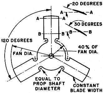
Fig. 5 - Ducted fan blade dimensions.
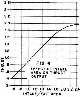
Fig. 6 - Graph of ducted fan thrust vs. Intake/Exit Area
ratio.
The next test was to find the most efficient position of the fan relative to
the duct inlet. With the fan at the edge of the duct inlet, a constant was obtained
with which the other positions were compared. With the fan completely within the
duct, the thrust dropped off 25%. With the fan 4% of its diameter outside the duct
inlet, the thrust was increased 34%. With the fan 8% of its diameter outside the
duct inlet, the thrust dropped 5% below the constant.
The next step was to test the effectiveness of various blade angles. Four tests
were made with blade angles ranging from 20 to 50 degrees. The 30 degree blade angle
produced the best results, with the 20 degree angle next best. A check was made
with smoke streams to try to find the cause of the drop in thrust at 40 degrees.
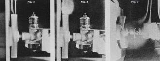
Figures 3 and 4. show what happened. Notice that in Fig. 3 the smoke is drawn directly
into the ends of the 30 degree blades and that in Fig. 4 the smoke is being blown
away from the ends of the 40 degree blades. Air was drawn into the front of the
blades in both cases, but the higher blade angles caused the blade airfoils to stall
and spill the air off the tips, thereby reducing the amount of air being forced
into the duct.
These tests were later run again with an Arden .09 turning at 13,000 rpm and
the same results noted, showing that the blades really weren't stalling at high
angles but were acting as paddles, throwing the air off the tips.
A series of tests was run on eight different fans, each having different blade
areas and diameters. The proper fan-diameter to exit-diameter was found to be 1.3
to 1 and the blade area 1.2 times the exit area.
To put this in simpler terms, the following relationship was worked out to get
the proper blade area and diameter with the exit diameter known (see Fig. 5). This
fan shape was decided upon because of the higher thrust output and the higher blade
speed near the tips. The center or hub section of a normal fan produced relatively
little thrust. Later we shall see how the hub of the fan shape chosen was altered
to increase thrust.
Having determined the most efficient basic relationships of the duct unit and
having boosted efficiency 44%, we made the following tests to find the best air-intake-area
to exit-area ratio. A graph (Fig. 6) was drawn and the various percentages of intake
area calculated so that the intake slots could be adjusted to match these areas.
The graph shows the results of the tests using a constant fan speed of 8,500 rpm.
Another test was made using the Arden .09 at J2,000 rpm with the same relationships
and gave practically the same results.
The thrust increase is proportional to the intake area increase from 0.8 to 1.8
times the exit area. Therefore, the minimum intake area should be not less than
2.0 times the exit area and the maximum area should not exceed 2.4 times.
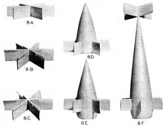
Fig. 8 - Ducted fan exhaust tube airflow straightener vane/cone models.
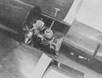
Fig. 9 - Ducted fan unit installed in model airplane.
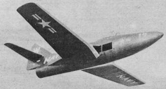
Fig. 10 - Ducted fan-powered model airplane in flight.
Aside from this, it was found that special intake ducts or tubes to direct the
flow of air to the fan blades did not increase the thrust output enough to merit
their use. Plain holes in the sides of the fuselage are easier to build and just
as efficient. Also, with the air intakes just outboard of the engine position, no
special cooling duct was needed. As Fig. 7 shows, the smoke is drawn straight in
from the sides of the fuselage (air intakes) to the engine and then rearward to
the fan blades. This provides sufficient cooling for the engine.
We had planned on using a center smoothing cone back of the fan to smooth out
the flow of air. Before testing this cone, it was decided to determine the effect
of flow straighteners on the thrust output. A six-bladed straightener (Fig. 8a)
was installed just inside the duct inlet and the thrust difference measured. We
had expected only a small increase in thrust. A 300% increase was measured.
If flat flow straighteners worked so well, how about cambered ones? A camber
of 20 degrees was built into the straighteners (Fig. 8b) so that their leading edges
met the flow of air off the blades of the fan. This resulted in an increase of 20%.
Next, 40 degree camber straighteners (Fig. 8c) were tried. This test produced an
increase of 5% over the 20 degree camber. Adding these figures shows that the use
of 40 degree cambered straighteners (Fig. 8c) produced a thrust increase of 325%
over the thrust obtained without any flow straighteners.
Experimentation showed that the depth of the straighteners had to be at least
one-third of the diameter of the duct inlet and that the curved portion nearest
the fan blades was 25% of this depth.
After the tests on cone shapes were completed, further tests on flow straighteners
were made and will be discussed later. The basic shape of the cone was determined
by rotating the fan at slow speed in open air and blowing smoke through the blades.
The smoke after passing through the blades., formed a cone about four inches long
and two inches in diameter. This was the shape of the first cone tested (Fig. 8d).
This produced a thrust increase of 25%. A new cone was constructed with a fillet
extending out the front of the duct tube to the hub of the fan (Fig. 8e). It produced
an additional increase in thrust of 24%. By moving the cone 8% of the inlet diameter
inside the inlet, thrust was increased another 10%.
Continuing along this line, another full-length cone was constructed with the
fillet at the front (Fig. 8f). With the same adjustments as on the other tests,
an additional thrust of 5% was recorded. The final cone was the length of the duct
tube. Then, as shown in Fig. 8f, four additional flow straighteners were added at
the tip of the cone with a resulting increase of 12% in thrust output.
At this point, the end of this series of tests, it may be interesting to see
just how much thrust output has been increased over the figure obtained at the beginning.
The original thrust output reading was 2.7 and the last reading was 22.9, an increase
of over 840%.
Here is a summary of the information obtained, laid out in the order necessary
for planning your ducted-fan model:
(1) A side view drawing of the proposed model should be laid out first. With
this, you can determine the largest duct exit diameter possible; this can be enlarged
in size because most scale models will leave the duct exit diameter too small for
practical operation. With Half-A engines it should be 2 1/4" to 2 3/4"; with .09
engines it should be about 3 1/2 "; and with .19 engines 4" to 4 3/4". We found
that the volume of airflow through the duct was more important than the speed of
this airflow. Therefore use the largest duct exit diameter possible with a given
engine and plane combination.
To determine the size of engine to use with your model, apply the same methods
used for conventional propeller-operated models. This system has very nearly the
same efficiency as a propeller. You see in Figure 10 a 30-inch Grumman Panther that
was built using this data. The model had a 1 3/4" duct exit and flew very well with
a K&B Infant engine although its weight was over 8 ounces.
(2) Next, the inlet diameter should be 1.2 times the exit diameter. The length
of the duct is not critical and is determined by the placement of the engine. The
fan diameter is 1.15 times the exit diameter, slightly smaller than the inlet. See
Fig. 5 for other dimensions. The fan position is such that the trailing edge of
the blades are 4% of the inlet diameter outside the inlet. See Fig. 1 for general
layout. Blade angles must not exceed 50 degrees. Start with 25 degrees and increase
if necessary.
(3) The cone diameter should be one-half the diameter of the inlet and its length
should be equal to the length of the duct. The front fillet on the cone should extend
out the front of the opening (duct), tapering to the hub of the fan. The six flow
straighteners should be mounted on the cone so that when installed in the duct they
are 8% of the inlet diameter inside the duct.
The depth of the flow straighteners should be one-third the diameter of the inlet
and the curved leading edge 25% of this depth, with a curve of 40 degrees opposite
the angle of the blades. The four rear-flow straighteners are attached to the tip
of the cone and have the same depth without the curved leading edge.
(4) The intake area should be between 2.0 and 2.5 times the exit area. Enlarging
the scale root intakes of the model is not enough. Additional intake area on the
sides of the fuselage is necessary to get proper intake area. This can be covered
by coarse screening and lightly doped for camouflage.
Place the engine approximately even with the wing root intakes for maximum cooling.
Figure 9 shows a closeup of our model used in the tests and the arrangement of the
parts. Small horizontal and vertical vanes fitted in the exit of the duct can be
adjusted to control the thrust direction.
With this data incorporated into your design, you are all set to begin construction
with the assurance that you will have a carefully-engineered and efficient model.
The author would appreciate receiving any comments and experience from anyone
building a model along these lines. Write in care of this magazine.
|


