|
|
August 1940 QST
 Table of Contents Table of Contents
These articles are scanned and OCRed from old editions of the
ARRL's QST magazine. Here is a
list of the
QST articles I have already posted. All copyrights are hereby
acknowledged.
|
Often when I see photos of some of the early radio control gear for model airplanes,
I have a simultaneous reaction of aghastness and marvel at the crudity and ingenuousness,
respectively, of the electromechanical devices - the same kind of reaction I have
to stories about early surgical procedures and equipment. In 1940, when this article
appeared in the ARRL's QST magazine, successful takeoffs and landings were
considered notable events not so much because of pilot ability (or inability), but
because of the low reliability of available electronic and mechanical gear. Vacuum
tubes with attendant heavy, high voltage power supplies, and heavy metal gears and
shafts required large airframes to support all the weight and bulk. A less than
greased-in landing usually resulted in a lot of repair to airframe and radio control
equipment. A modeler had to build (and often design) his own radio and electromechanical
actuators since commercial availability was sparse. Modern-day low-cost, readily
available R/C models incorporate, depending on your requirements, autopilot, total
prefabrication of airframe, propulsion, and guidance components, all of which places
the burden of success entirely on the operator and none on the airplane. BTW, dig
Mr. Bohnenblust's ride in that photo!
New Radio Control Gear for Model Airplanes
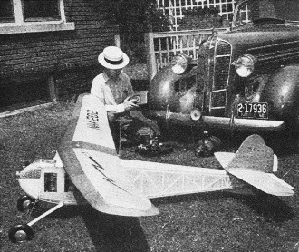
The gnome, "A chain is no stronger than its weakest link," still
holds water when it comes to radio-controlling a ship. The author is shown giving
each component the once over. Note the belt-driven generator run from the Dodge
driveshaft.
Three-Way Control Installation for Gas-Powered Models
By C. E. Bohnenblust, W9PEP
The control of machines by radio has been a fascinating field of endeavor for
a long time, but not until the last couple of years has there been really fool-proof
radio control of planes by amateurs. This story is the result of a mighty interesting
demonstration staged at the Midwest Division Convention held at Wichita in April.
Since then successful flights and landings have been executed, and as we take off
to press Siegfried and Bohnenblust are vying with the best of them at the National
Meet in Chicago.
About eighteen months ago Mr. C. H. Siegfried approached me with a request to
assist him with the design and construction of radio control gear for his model
gas-powered planes. Siegfried is a model builder of great ability and his planes
fly - something quite vital before radio control can be applied to a plane. I became
interested in the job and this article describes the gear we are using, its adjustment
and operation.
The Receiver
The receiver, with minor changes, is identical to that shown in a previous issue
of QST.1 The use of the RK62 tube in a conventional "super-regen" circuit
provides a consistent receiver which will operate the Sigma relay at distances of
slightly over a mile on level ground. The circuit is given in Fig. 1.
The receiver, less the relay, is assembled in a 2 3/4-inch diameter aluminum
shield can. A hole through the can allows the tube to protrude an inch or so. The
base is fitted with a plug so that the entire receiver can be easily removed.
The antenna is coupled to the receiver by means of a three turn coil. We found
this to be somewhat better than capacity coupling. An air tuning condenser of about
15 μμfd. capacity connected from the center of the coil to the plate end,
with the rotor connected to the center of the coil, makes tuning easier since hand
capacity is largely eliminated. A hole cut through the base of the can provides
access to the tuning condenser for adjustment. The antenna is vertical and about
three feet long. No potentiometer is used for plate-voltage control, nor is an r.f.
choke used.
The large-size "D" flashlight cell is used for the filament supply because constant
voltage for the filament is very essential for continuous, stable receiver operation.
A medium-size cell might be used with satisfactory results. However, a "penlite"
cell is not satisfactory. Note that but one cell (1.5-volt) is used for the filament.
We have found this to be as satisfactory as higher voltages.
A five-ounce 45-volt "B" battery is used for the plate supply. This size will
last for some time.
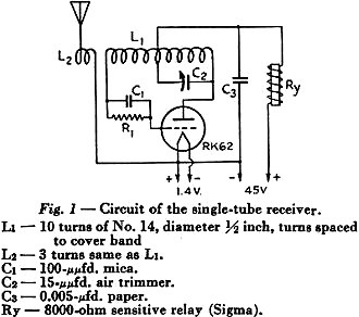
Fig. 1 - Circuit of the single-tube receiver.
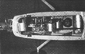
The complete control set-up installed in the model plane. The
third motor (throttle control) is mounted to the left of the control mechanism.
At the right are the relay and the receiver, the latter completely enclosed, except
for the tip of the tube, in a shield can.
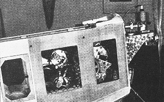
A side view of the plane with the control unit in place. This
shows the opposite side of the unit to that given in the other photograph. The commutators
and wipers on the motors are visible through the left window, while at the right
are the 10:1 gears, the escapement assembly, and the magnet which operates the escapement.
The throttle on the engine is controlled by a cord driven by the electric motor
mounted at the front of the plane.
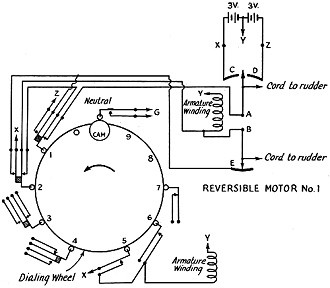
Fig. 2 - The electrical circuit of the control unit. Motor No.2
is not shown because its connections are similar to those of No. 1.
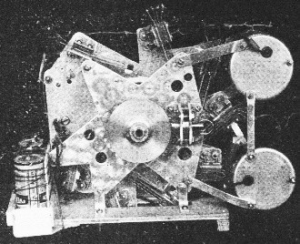
The control unit, showing batteries and two of the reversible
motors. The 4:1 bevel gears are mounted on the front plate; the hook for the rubber
motor is on the right-hand end of the shaft of the driving gear. Spring contact
assemblies are attached to the rear dural plate. At the top, one of the assemblies
can be seen riding on the rim of the dialing wheel.
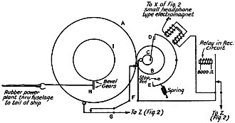
Fig. 3 - The mechanical gear system and control escapement.
Adjustment of this receiver is simplicity itself. Starting with no signal and
with loose antenna coupling, the plate current will be well below 1.5 milliamperes.
Coupling is increased until the plate current is about 1.5 ma. Then, with the carrier
on, the signal is tuned in. This results in a lower value of plate current. Some
readjusting of antenna coupling may now be necessary to hold the plate current at
1.5 ma. with carrier off.
Try other values of grid leak until the value is found which gives greatest plate
current change. To do this it is probably best to separate the transmitter and receiver
some distance from each other.
The Transmitter
The transmitter is of conventional design, using an 807 doubler in the final
for 5-meter output. Using a 500-volt power supply, about 20 watts output is obtained.
An 89 with a 20-meter crystal drives the 807.
The transmitting antenna is a "J" type. This is equivalent to a vertical which
gives coverage in all horizontal directions.
The Control Unit
The control unit presented by far the most difficult problem of the entire job.
There are of course many methods of applying the controls, and final choice of the
method used was influenced by (1) weight, (2) speed of application, (3) ease of
construction, (4) consistency of operation, and finally (5) controllability.
Our first was a simple rudder control unit which operated in sequence each time
the carrier was turned on. The sequence was (1) neutral, (2) right rudder, (3) neutral,
(4) left rudder, (5) neutral, and so on. Such an arrangement has been used by several
experimenters with good results, and since constructional data have appeared previously
no details will be given here.
With the simple rudder control we obtained several nice flights; however, we
soon concluded that we needed more controls to do the job up "brown." After much
discussion we decided upon the following controls: (1) rudder right or left, (2)
elevators up or down, (3) motor speed high or low, and finally (4) shut off motor.
The use of but one receiver makes a pulsing or "dialing" arrangement necessary
in order to select and operate anyone of several spring assemblies. Pulses for this
unit must be made uniformly in order to avoid interference with the restoring feature.
This will be explained later. We use an ordinary telephone dial to pulse the carrier.
A switch turns on the carrier, then by dialing a number the carrier is pulsed. This
rate of pulsing is about 9 per second.
Rather than using a stepping switch, actuated by an electro magnet, a dialing
wheel driven by a rubber motor is used. Its rotation is controlled by an escapement.
This device is lighter and the battery required to operate the escapement is smaller.
Thus an overall saving in weight is effected.
Reversible electric motors were decided upon to apply the controls. Model DC-7
electric motors, manufactured by the Pittman Electrical Developments Company, Philadelphia,
Pennsylvania, are used in this unit. Three separate motors were used. These motors
weigh three ounces each and come equipped with reducing gear assemblies. The speed
is reduced to one revolution in 18 to 20 seconds. By using but 1/20 revolution to
apply the control the time required is about one second.
Motor shut-off is obtained by opening the ignition circuit sufficiently long
to cause the motor to die. Then other controls may be selected.
Now for the hard part of the job. A dialing wheel about three inches in diameter
carries a cam which, when the wheel is rotated, successively operates the spring
assemblies. The operation of the spring assemblies in turn closes electrical circuits
to the motors which apply the controls. Fig. 2 shows the circuit arrangement for
motors Nos. 1 and 3. The circuit arrangement for No. 2 motor is identical to No.1
and is not shown.
Reversible motor No. 1 has two wipers, A and B, attached. These wipers engage
commutators C, D and E respectively. It will be noted that C and D are spaced apart
just far enough so that wiper A can rotate to the center gap where it clears, electrically,
segments C and D. Wiper A, segments C and D and the normally-closed contacts at
positions 1 and 2 constitute the automatic restoring feature for motor No. 1. By
tracing the circuit it will be seen that, with 1 and 2 at normal, if wiper A is
in contact with either C or D, the circuit is closed to the motor so that it rotates
to the gap between C and D, which is normal. The rudder is adjusted to normal with
the motor in this position.
Rotation of the dialing wheel to bring the actuating earn to position 1 operates
the spring assembly at that position. Operation of this spring assembly opens the
restoring circuit and closes a circuit which causes the motor to rotate to the right.
It will be noted that this circuit is in series with commutator segment E and wiper
A which open the circuit when the motor rotates a given amount. This position is
of course determined by the length of segment E and determines the amount of right
rudder applied.
The control remains operated so long as spring assembly No.1 remains operated,
and when the spring assembly is released will rotate back to normal as described
above.
Operation of spring assembly at position 2 results in rotating the motor to the
left for left rudder control in a manner identical to that described above for right
rudder control.
Motor No.2 is an exact duplicate of No.1 and is wired to the spring assemblies
at positions 3 and 4 exactly as shown for motor No. 1. This motor controls the elevators.
Motor No.3 rotates right or left as spring assemblies at 5 and 6 are operated,
respectively. This motor is connected to the throttle and has no automatic restoring
feature, since after setting the throttle at a given point it would not be desirable
to have it rotate back to "neutral" automatically. This arrangement makes possible
the setting of the throttle at any given point.
The spring assembly shown at position 7 is used to open the ignition circuit
of the motor, which of course causes it to die.
The Mechanical System
Fig. 3 shows the gear layout and the escapement. Gear A is on the same shaft
as the dialing wheel shown in Fig. 1. Gear A drives gear B in the ratio of 10:1.
Gear H, driven by the rubber motor, drives gear I, which is also on the same shaft
as the dialing wheel and gear A. This ratio is 4:1. Therefore 4 turns of rubber
are used to turn the dialing wheel one revolution.
The dialing wheel normally cannot rotate because the "flipper" D strikes the
edge of the escapement. When the magnet is energized the" flipper" clears and is
caught by E of the escapement. This permits the dialing wheel to turn nearly 1/20
revolution and the cam is now located at position 0 shown in Fig. 2. One pulse of
the magnet similarly rotates the dialing wheel to position 1. Likewise by pulsing
the magnet the dialing wheel cam can be rotated to any position from 1 to 9. The
pulsing of the magnet obviously is accomplished by the relay in the receiver circuit.
Position 0 is left dead because in operation the carrier is first turned on by
use of a non-locking switch and then the dial is operated to pulse the carrier.
Because of the interval of time involved before the dial is operated, a spring assembly
at position 0 would be operated an appreciable length of time.
It will be noted that the cam on the dialing wheel is at position 0-9 inclusive
only when the carrier is on and the magnet operated, holding the "flipper" at E.
Therefore the control selected is on so long as the carrier is on. When the carrier
is released the" flipper" rotates to normal. However the cam C on the same shaft
with the" flipper" closes spring assembly F through normally closed assembly G.
This causes the magnet to operate and thus the escapement is automatically operated
until the cam on the dialing wheel reaches neutral, whereupon assembly G is opened.
This stops the dialing wheel at neutral. Note that spring assembly G shown in Fig.
3 is the same assembly as shown in Fig. 2.
The automatic restoring of the dialing wheel to neutral as described above does
not interfere with dialing so long as "carrier off" time interval of the pulsing
is not too great. Pulsing the carrier means simply cutting the carrier off for a
short time (about 1/18 sec.) and then restoring the carrier. The carrier is left
on about 1/18 sec. and this cycle repeated as desired for the various controls.
During the "carrier off" intervals of pulsing, the magnet is released and the
"flipper" rotates to normal. This closes spring assembly F which operates the magnet
even though by this time the carrier may not be on again. However in order to avoid
interference the carrier must be on again before assembly F opens. If interference
is experienced, shorten the "carrier off" time of the pulsing or add some weight
to some of the moving parts to build up inertia which of course will slow down the
speed of rotation of the dialing wheel.
One turn of the dialing wheel (four turns of the rubber power plant) is required
for each operation. It will be noted that all the spring assemblies are operated
when selecting a control; however, the time closed is so short that the controls
are not applied. If a control would be slightly applied in this manner, the restoring
device .would immediately bring it back to neutral.
Reviewing the operation we have this sequence:
1. Carrier is turned on. Cam on dialing wheel rotates to position 0.
2. Carrier is pulsed; cam is rotated to positions 1-9 corresponding to the number
of pulses.
3. With carrier left on cam is held at that position which applies control.
4. Carrier is turned off. Cam wheel rotates back to neutral, and simultaneously
the control applied restores to neutral.
The operation of the spring assembly at position 7 when the dialing wheel is
restoring to neutral is but momentary and not of sufficient time to kill the motor.
The weight of the unit is two pounds. The receiver and batteries bring the total
weight up to 3 1/2 pounds. The ship has a wing spread of 12 feet and weighs 13 1/2
pounds complete with the radio and control unit.
This solution of the control-unit problem, I feel, is all that the experimenter
could expect from a performance viewpoint. However, I do believe that the same performance
could be duplicated in a strictly mechanical unit without the use of the electric
motors. Such a solution would be lighter and less costly. I hope to have something
along this line in the near future.
1 DeSoto, "Radio Control of Powered Models," QST, October, 1938.
|


