|
There is no simpler
introduction to functional model boating than an airboat - especially if you are
already familiar with the operation of glow fuel (or diesel) engines that have airplane
propellers mounted to them. They are started and adjusted that same way as with
an airplane, and all the mechanical complexity and need for waterproofing prop shafts
and rudder connections is avoided. It is for those very reasons that my first-ever
radio-controlled craft back in the mid 1970s was an
airboat that I carved out of blue
foam and covered with Solarfilm (remember that stuff?). It had a Cox Babe Bee .049
mounted on a pylon in a pusher configuration. We lived two blocks from Bear Creek
in Mayo, Maryland, so there was easy access to water. For that matter, whenever
we had a really big rain, the water would pool way up in the road and surrounding
yards so that was available for use as well (not that the grown-ups were happy about
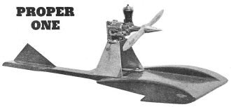
all the water - or the noise my boat made). This cleverly named "Proper One" airboat
article and plans appeared in a 1960 issue of American Modeler magazine.
It is much nicer than the kludge I threw together.
Proper One Air-Prop Racing Boat

Air-prop racing boots are a snap to construct, great fun to operate;
Bill LeFeber presents his Half-A wonder...
By Bill LeFeber
Yup, the air-boats are coming! Make no mistake about it, they will seriously
challenge the water-prop hydros, and soon. Admittedly, there is more ground to cover
in experimentation, but the gap is narrowing. Charles Oslanci has clocked 94 plus,
so that "impossible" 100 mph is definitely within reach. This with a water-prop
type hydro, but Fred Goodman has done 70 with an air-prop job. Considering the late
start that air-proppers had, this is not bad. Considerable headway has been made
in the 1/2A category, as the mark of 52 mph by Chadd Rector of the Indianapolis
MPB Club with an air-boat eclipses the water-prop mark by almost 15 mph. Chadd used
the ubiquitous Cox "Thermal Hopper" .049 in clocking this hot mark.
Interested in making a simple Air-Propper that will get out and really rip? Pull
up a chair, bud, and we'll tell you how.
One block of balsa, 1 1/2" x 1 1/2" x 8" makes a single sponson, so either tack-cement
two blocks together or use a 3" thick block so that both sponsons can be cut simultaneously
on a bandsaw (or power jigsaw). If a 3" block was used, carefully mark the center
line and cut in two to obtain both sponsons. Mark dowel locations with care and
drill to required depth, using 1/8" dia. drill. The sponson to be used on the inside
of the circle (tethered side) is trimmed 1/16" on the bottom face now. This is for
the 1/16" plywood, which is now added. Why? Because any real speed merchant will
tell you that flat surfaces are highly desirable, and balsa gets pounded and nicked
out of shape very quickly. This inner sponson takes the main pounding when under
way, you know, so the plywood is really necessary. Once the glue job has had a good
chance to dry, use 1/8" dowels to join the two sponsons together (temporarily) so
that sanding simultaneously will result in identical-shaped sponsons.
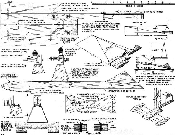
The main part, or center section, is cut out as per the plans and shaped as shown.
Now before you dowel and glue the sponsons to the center section, let me give you
a tip on glue jobs. From the pounding that hydro jobs have to take, it has been
found that only Weldwood or Elmer's two-part glue (or similar high grades) will
do the job right. Both take a good 12 hours to dry, but the joint will be stronger
than with standard cements.
The next item is the 3/32" plywood rudder. This rudder may stabilize the model
a little at high speeds, but the main reason for it is simply a hand-hold to insure
successful launches rather than dunkings. The dowel-and-glue joints are there for
a reason, so don't omit any of them. The sponsons and rudder can now be dowelled-and-glued
to the center section; put the entire assembly aside to let the glue set well while
we go on to the pylon engine mount and bridle-making.
The pylon engine mount is light and of low drag. Either aluminum (as the drawings
show) or 26 gauge galvanized iron sheet metal can be used for this item. Either
will do the job well. Using the material of your choice, scribe the outline shown,
cut and bend to shape. The sharp edges resulting from snipping it to shape should
be removed via a brisk session with some emery cloth. This will reduce the chances
of sliced fingers later on. Another item to keep in mind is that the drilling of
holes in the pylon mount will be much simpler before the final bending is done.
The use of slots where shown will simplify minor balancing of the hull later.
At this point a choice will have to be made as to which engine will be used to
power this model. Our recommendation would be one of the Cox engines, such as the
"Thermal-Hopper" or "Space-Bug." If, however, you have a Holland "Hornet" or Atwood
"Shriek" handy, they will pull this hull around just fine. Remember that the Cox
engines have a tendency to run in either direction, so it will be necessary to check
the direction of the prop blast before releasing.
The actual engine mount should be an extruded aluminum angle if you can obtain
it. If bent from sheet metal, it will be found that the bend will crystallize from
the high-frequency vibrations of the engine, minor as they may be. The extruded
mount will outlast the bent type by many times. The 2 degrees offset of the engine
is not mandatory. If you do not care to offset the engine, take care that if faces
dead straight ahead; pointing the engine into the tether circle will encourage many
dunkings.
Now comes the most important stage in the whole construction bit. The longitudinal
position of the engine mount pylon. The pylon, engine, prop, extruded prop mount
(and tank, if separate) are all assembled now. Using rubber bands or Scotch tape,
attach the pylon to the hull temporarily so that a wire "hanger" can be used to
check the tilt of the whole works when suspended above a desk or other horizontal
item. The front of the, hull should be about 5" above the lowest point (the very
rear end) of the hull. See hull balancing detail on plane. If a slightly larger
engine is used, the difference can be 6" or 7". Since the Cox line of engines are
light, 4" to 4 1/2" will be alright for them.
See detail "A" for the attachment method for fastening the pylon mount to the
hull. Use your own idea if you make it substantial. Blind mounting nuts are okay
if the hull is fairly firm balsa, but if you used soft balsa, the 1/4" dowel system
is far stronger. A detail on the plans shows the proper bridle needed for this model.
Do not use another type unless you have prior experience in high-speed hydro running.
The pylon mount should now be removed from the hull and the finishing paint job
be done. Two coats of Dulux "Prepare-A-Coat," followed by Wet-or-Dry sanding, will
generally slicken up the surfaces to an acceptable degree. Spray on two more coats
of Dulux Enamel, allow to dry thoroughly, and you are ready to race. Any other brand
of finish is fine, providing it is a "hot-fuel proof" type.
The bridle can be solid or stranded wire. If you experiment, use strong fishing
line until the design is finalized - then make up a permanent wire type. For competition
runs, stranded cable is a "must." And figure on a 26' 3" radius from the center
of the hull to the center of the running pole. Four laps at this radius equals 1/8
mile, giving you a basis for timing runs. In running this design, it will be found
that the best starts will be made with the rear end of the hull partly submerged
and the sponsons just about clearing the water. A push, holding the rudder and keeping
the tether line fairly taut, will send her off screaming.

Proper One Air-Prop Racing Boat Plans
Full size drawings
are on Hobby Helpers Group Plan #460
Posted April 30, 2022
|


