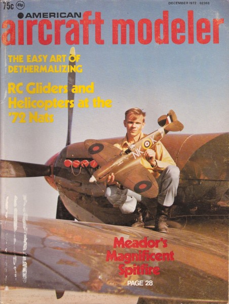
|
Website visitor Garry O. wrote
to request that I post this article from the December 1972 issue of American
Aircraft Modeler magazine featuring the Vickers-Supermarine Spitfire Mk
IIA. With its elliptical wing planform and outward-retracting landing gear, is considered
one of the most attractive airplanes ever to come out of England. It, along with
the North American Mustang, are probably the two most modeled fighters from World
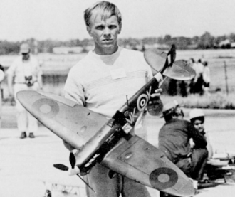
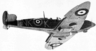
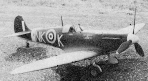
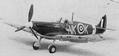
War II. This .61-powered control-line model by Malvin Meador won the 1971 Nationals
for control-line scale. It has operating retractable gear, flaps, sliding canopy,
navigation lights, and drop tanks.
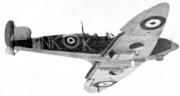
Vickers-Supermarine
 Spitfire Mk IIA - Plane on the Cover Spitfire Mk IIA - Plane on the Cover
Model that won the '71 CL Nats and was 6th at the '72 CL Scale World Champs is
patient project of a great plane. Has many operating features and flies quite well.
By Malvin Meador
Photos by Bill Boss and the Author
Every Scale builder has a favorite airplane or type of airplane; I've always
been inclined toward World War II military aircraft. After moderate success in local
scale contests, I decided to build a ship for entry in the 1971 Nationals. To do
this, I needed a subject which inspired me to invest the amount of time required
to complete a competitive scale model. Retractable landing gear - an operating feature
having good spectator appeal and a high scoring flight demonstration option - was
a must. Another point relevant to selecting a subject was additional operating features
such as flaps, sliding canopy, navigation lights, drop tanks, etc., which could
be incorporated. Also, I wanted to stay away from subjects which had been overdone.
One aircraft kept coming to mind, the Supermarine Spitfire. It was one of the
most famous World War II fighters, plenty of reference material was available and,
despite its fame, it didn't enjoy much popularity with modelers. The Spitfire had
enough operating features to insure a respectable scale flight score, and it featured
very simple retractable landing gear which could be easily adapted to Bill Johnson's
efficient, lightweight Centrak gear retraction unit. Using this system would eliminate
the mess of batteries, extra control lines, electrical wiring, and other assorted
headaches which go with retractable gear in control line models. Also, the simplicity
of the landing gear would make it fairly easy to machine scale shock absorbing gear
struts for added realism.
Nice facet of real plane was its plywood covered wings. Detailing
is complete without yards of rivet lines.
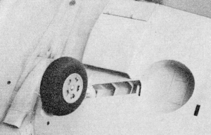
A Bill Johnson Centrak gear is used. At speed in flight, centrifugal
force working against a spring raises the gear. Very reliable.
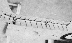
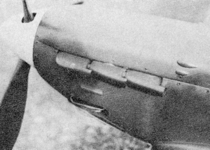
With flaps down one sees even more detail, including flap position
indicator finger which lifts through a coyer on wing top surface. Oil cooler door
also operates.
All smooth areas of the model are fiberglassed, including some
detail items such as simulated exhaust stacks.
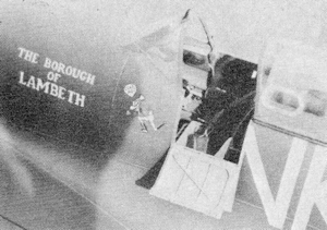
Before surface finishing, cockpit interior is completed. Door
hinges open to reveal many more details, note canopy slides back.
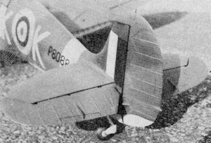
All control surfaces have simulated fabric covering. Note full
swiveling tail-wheel.
While considering the positive and negative aspects of the Spitfire as a flying
scale project, one nagging thought kept coming to mind: The extremely short nose
moment, small empennage areas, and fore and aft placement of the landing gear on
the prototype could make the model's flying characteristics less than satisfactory.
However, after reading a very scientific conclusion that "anything will fly on control
lines," I decided to proceed with construction. The resulting model did fly satisfactorily,
but it is definitely not a beginner's ship-the Spitfire demands the flier's undivided
attention from takeoff to the end of the last taxi lap.
Which variant of the Spitfire to build was the final problem. The solution was
dictated by the availability of reference material, and I settled on the Mark IIA
depicted in Profile Publication, No. 41. Several variants of the Spitfire
shared a basic airframe; it is simple to convert the Mark IIA to a Mark I, III,
or V, and substitution of four 20mm cannons for the inboard .303 caliber machine
guns converts the model to a Mark IIB.
Before beginning construction, study every available publication on the Spitfire
to become familiar with details of the prototype. I found the following references
to be particularly helpful: Bruce Robertson's Spitfire: The Story of a Famous
Fighter, and Aircraft Camouflage and Markings, 1907-1954 both available from
Harleyford Publications; Profile Publications, Nos. 41 and 166; Aero Publisher's
Supermarine Spitfire; and Willis Nye's excellent drawings of the Spitfire. These
publications contain many drawings and photos invaluable for detailing the model
and preparing the proof of scale presentation which must accompany it in competition.
Construction may be greatly simplified with installation of conventional non-retractable
gear. However, the satisfaction of seeing the wheels disappear into the wings shortly
after takeoff makes the extra effort worthwhile. If you use the Centrak installation,
contact Bill Johnson, 2504 Charwood St., Charles, Mo. 63301. Bill is familiar with
the model and can supply the retract unit and complete instructions for installation
and operation.
At Nats, Malvin won scoring 517 points. He also won Sterling Award for highest
static points.
Construction
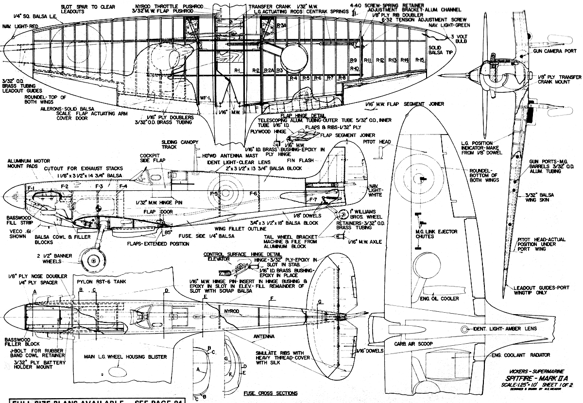
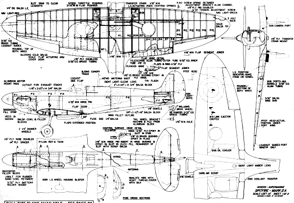
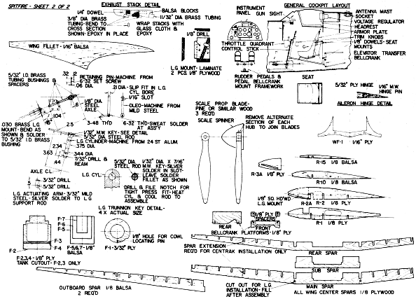
The landing gear is the most complicated component and is a good place to begin.
The gear struts are turned from aluminum stock and a 7/32" diameter bore drilled
and reamed for the oleos. Drill holes for the oleo retaining pin and the gear support
rod, making sure the centerline of each hole is at the proper angle (see plans).
This is necessary for correct tracking of the wheels and for maintaining correct
gear geometry during retraction.
The oleos are machined from mild steel (I used 5/16" steel bolts). and the axles
are 1/8" music wire threaded on both ends and silver soldered into tapped holes
in the oleos. Exercise caution when drilling the holes in the oleos to insure correct
alignment of each component. File the top of each strut to the shape shown, and
assemble the struts and gear support rods, keying in place as illustrated in the
plans. Fabricate the spacers, bushings, and mounts from brass tubing and sheet and
the gear actuating arms from mild steel; assemble, making certain that the gear
mounts rotate freely on the support rods and that the actuating arms are silver
soldered in place at the correct angle. Selection of springs for the oleos depends
on the final weight of the model and the amount of shock absorbing action desired.
The oleos can be removed easily, so experimentation with various springs presents
no problem.
One further note on the landing gear: If the Banner wheels shown on the plans
are used, the aluminum hubs must be faced off on each side to give a thinner contour
and allow the gear to retract fully into the wheel wells.
The wing contains almost all the gear, flap, and other control operating mechanisms
and is the next component to build. Cut ribs R-2, R-10, and R-15 to shape and drill
1/8" holes in each one at the location shown on the plans. Stack the correct number
of 1/8" balsa rib blanks in sequence with the pattern ribs, using 1/8" dowels to
maintain alignment. Shape the stack of ribs in the usual manner, with one exception:
The stack should show a curve, top and bottom, from the root to the tip rib. This
is because the upper and lower wing surfaces are curved as viewed from the front.
Join the balsa wing spars and plywood doubler, and glue the ribs in place on
the spar. Use two 20" lengths of 1/8" doweling in the holes previously drilled in
each rib to maintain rib alignment until the glue dries. When dry, notch the ribs
and install stringers for the flap wells and aileron cutouts.
The bottom surface of the outer wing panels should be sheeted next. Leave the
bottom center section open until the wing is in place on the fuselage and all control
linkages are hooked up and operating properly. The flap and aileron wells should
not be cut out until the tops of the outer wing panels have been covered and the
wing sanded to shape.
Cut the openings for the landing gear wells in the bottom of each wing and remove
sections of ribs as required. Then line the wells with 1/16" balsa. To install the
landing gear, it is necessary to cut a small hole in the wing bottom sheeting between
the leading edge and front spar. Before final gluing of the plywood landing gear
mounts, check gear alignment carefully both in the extended and retracted position.
Mount the Centrak unit with the Roberts Flight Control, control line leadouts,
and control linkages attached. Bend and install the 3/32" music wire gear actuating
arms. Be certain that e rods are the correct length to actuate both gear simultaneously-they
m s: both be full up and full down at same time. Install the Centrak spri leaving
the end which attaches to control unit free. This will allow ' r movement of the
landing gear to check for proper fit in the wheel wells as construction progresses.
Now is the time to install linkage for moveable ailerons, navigation lights and
wiring, flaps, etc., if you wish. The wing tip lights on the original were left
hanging from the end of the wing until the tips and top covering were in place and
the wing shaped. They were then epoxied in place, covering the bulb completely with
epoxy. When dry, the epoxy was filed and sanded to form the lens and housing, and
the entire area was painted the color of the lens. (Red on the left wing and green
on the right wing. Mask the lens area, and paint the surrounding area silver. The
silver dope is covered by the finish coat later and allows light to shine through
the lens but not the surrounding area.
The fuselage is constructed of balsa blocks glued to a built up crutch. The
various blocks are tack glued in place and the entire fuselage is carved a sanded
to shape, using cross section templates. After shaping the fuselage, remove the
blocks and hollow as much as possible without sacrificing strength, particularly
in the aft sections of the fuselage. Shape and glue 1/16" formers inside the blocks
in the positions shown on the plans. This provides stiffness without adding excessive
weight.
Epoxy the fuselage crutch to the wing, lining the wing up carefully to insure
correct incidence and planform alignment.
The horizontal and vertical stabilizers can be built up, or made by laminating
two 1/8" balsa sheets with a hollow 1/4" balsa core. I tried both methods, and the
weight difference using the latter method is negligible if you choose your wood
carefully (Sig contest balsa was used on the original). The elevators and rudder
are solid contest balsa, hinged as shown on the plans. This type of hinge is slightly
difficult to construct, but it closely approximates the hinges used on full scale
aircraft.
Glue the empennage in place, complete all linkage hookups, and install all lower
fuselage blocks and wing center section sheeting. Note that the bottom center wing
covering is flat at the front and blends to an inverted gull section at the flaps.
Most of the cockpit details on the original were finished prior to installation
of the upper fuselage blocks. When the cockpit area is finished to your satisfaction,
glue these blocks in place, add the wing fillets, and the model is ready for finishing.
I used Sig polyester resin and fiberglass cloth on the original. I have tried many
finishing methods, and found that the use. of fiberglass results in an extremely
tough model, requires less time than dope and silk, and makes detailing (such as
scribing panel outlines) much easier. The finished model, ready to fly, weighed
in at six lb. 12 oz. which compares favorably with other models of this type. The
use of fiberglass doesn't present a weight problem if it is applied sensibly.
To finish the model using fiberglass, give the airplane a final sanding, making
certain that all contours and shapes are correct. Cut a piece of glass cloth slightly
larger than the area to be covered, lay it in place, and coat liberally with polyester
resin. The cloth to cover the adjoining section should overlap with that already
applied. Sand the resin in the overlap area to insure good adhesion.
After completing the first coat, sand the entire coating with coarse paper (80
grit aluminum oxide paper works well) to remove gloss and rough edges. Use a sanding
block where possible to maintain the basic contours of the model. Apply a coat of
resin only, and wet sand with 220 and then 320 wet or dry paper. The model is now
ready for a coat or two of clear dope followed by color. I used Pactra military
flats with excellent result.
One final note on finishing. Component parts such as ailerons, flaps, elevators,
rudder, etc., should be as nearly finished as possible before installation. I try
to have them ready for the final color coat before attaching them to the model.
This requires the builder to apply the finishing steps outlined above to certain
parts of the model such as aileron wells, flap wells, and horizontal and vertical
stabilizer trailing edges before finishing the adjacent area. Care must be exercised
when fiberglassing and painting to prevent spoiling an already finished area.
<click for larger version>
<click for larger version>
Notice:
The AMA Plans Service offers a
full-size version of many of the plans show here at a very reasonable cost. They
will scale the plans any size for you. It is always best to buy printed plans because
my scanner versions often have distortions that can cause parts to fit poorly. Purchasing
plans also help to support the operation of the
Academy of Model Aeronautics - the #1
advocate for model aviation throughout the world. If the AMA no longer has this
plan on file, I will be glad to send you my higher resolution version.
Try my Scale Calculator for
Model Airplane Plans.
Posted January 21, 2012
|