|
Here is a really unique control line scale model project. This one
involves two separate airplanes and two separate pilots - one to
fly the twin-engined C-46 Commando tow plane and the other to fly
the CG-15 troop glider while it is attached via towline, and then
released for landing. Doing so is no different than two aerial combat
pilots chasing each other around the sky. The troop glider has its
own elevator control and also uses a third line to release the tow
line attached to the C-46. Anyone who has seen an R/C power plane
tow an R/C glider knows that coordinating the flight paths of both
aircraft can be very challenging. Most attempts to tow a free flight
(uncontrollable) glider behind a power plane end up in disaster,
so that is why a second pilot is needed for the troop glider.
 While
at the 2014 airshow in Winston-Salem, NC, Melanie and I toured what
was said to be by the attending aircrew that last remaining flyable
C-46. If you click on the thumbnail to the left, you can see some
of the photos I took of the interior. While
at the 2014 airshow in Winston-Salem, NC, Melanie and I toured what
was said to be by the attending aircrew that last remaining flyable
C-46. If you click on the thumbnail to the left, you can see some
of the photos I took of the interior.
Troop Glider and C-46 Tug
A most unusual scale CL project, the once-common Curtiss C-46
Commando twin-19-powered profile model for towing a true-scale replica
of the infamous CG-15 glider.
By Frank Scott
|
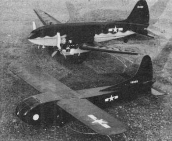
Each model is a complete control liner in itself. Glider
might whip control also.
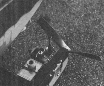
Quick-fill tank useful to assure equal and complete engine
runs. Top off before flight.
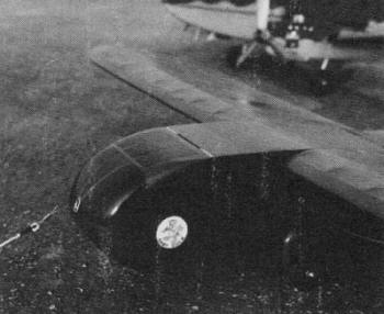
Third-line control in glider is essential for releasing
tow line. Two pilots needed.
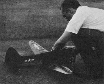
With the Commando, always start left engine first, especially
if you are right-handed.
|
Some called them "Whisper Ships" and others knew them as' "America's
Answer to the Kamikaze." The troop-carrying glider provided a unique
chapter in military aviation.
Widely used by both sides in WW II, the troop glider filled a
void in transport design.
Through their hinged noses they could easily load large, bulky
items such as jeeps and small bulldozers, which conventional cargo
airplanes, regardless of size or power, simply could hot carry.
The glider also could be landed in small, unprepared areas and,
because of its much lower cost, could be expendable.
Built by the thousands by furniture and piano factories, as well
as by more traditional aircraft sources, these almost helpless craft
served well throughout the war. Their exploits in Normandy and Burma
are still remembered. However, the gliders now have been totally
replaced by assault transports, improved parachuting techniques,
and helicopters. The troop glider is gone and few will mourn its
passing.
To fly a replica of these gliders on control lines, no unusual
skills are involved, and the price of an engine is saved. Instead
of pulling a free flight glider behind a control line ship (as has
been attempted before, with disastrous results), this glider is
built as a normal control line model which is simply towed by another
plane. This duplicates full-size practice in that each plane has
its own controls and its own pilot.
The CG-15 can be pulled by either a 35-powered, single-engined
model or a lightly-loaded twin with a pair of 19's (such as the
C-46 Commando, also presented here). Directions for the glider construction
are given first and in greater detail, since it is the more unusual
of the two airplanes.
Construction
The CG-15 was chosen for modeling instead of its better-known
predecessor, the CG-4a, because the CG-15 with its shorter wing
and less complicated landing gear seems more suited for control
line flying. Since I have a large factory drawing of this machine,
scale fans may be interested to know that this model is essentially
scale, even to the point of using a scale airfoil section.
Construction is not at all complicated. Although the model has
no pounding engine trying to shake it apart, use as much care in
its building as if it did, for it weighs as much and has much the
same flight loads as the airplane pulling it. Begin by gluing the
doublers and uprights to the fuselage sides. While they dry, bend
the landing gear and attach it to the landing gear mount.
The tow release is a simple third-line-operated device consisting
of a base and latch, spring-loaded in the closed position, and actuated
by the third line on a compound bellcrank as described in the March
1969 AAM. This assembly is easily made but it must work smoothly
to assure consistent operation.
Begin by making the base of 1/32" aluminum, as shown. As an alternative,
1/8" plywood may be used. When the tow-release base has been made
and bolted with 4-40 screws to the control platform, solder the
1/16" dia. wire latch to the 3/32" dia. brass tube pivot. Then,
after putting the .025 torsion spring into position, mount the latch
assembly to the base with a 1/16" wire pin. The upper end of the
latch is secured by a length of lead out cable to the third line
bellcrank. Assemble the landing gear mount to the control platform.
Next, add the tow release and compound bellcrank to the control
platform and hook up the controls. Assemble the sides to the platform
and add the cross braces to give the fuselage its boxy shape. Finish
roughing out the fuselage by covering the bottom, placing wing strut
wire, and adding the tail wheel. If a two-piece strut, spliced in
the center with brass tubing, is used, the struts may be left off
until later. The pushrod, elevator and stabilizer are assembled
before the top of the fuselage is covered with 1/8" sheet balsa.
The nose is carved from blocks for needed weight, although a nice
touch would be to stretch-form the nose from clear plastic. This
nose can be hinged, as the real ship's was, or detachable with dowel
pegs and rubber bands to permit access to the tow hook and control
system.
For all tail surfaces, use 1/8" hard sheet to save weight in
the tail, even though the plan shows the thicker section of the
real airplane.
The straight wing is built with a full-depth notched spruce spar
and notched leading and trailing edges. Provide holes in the root
and adjacent ribs to accept the dowels from the fuselage. The scale
fan may wish to cover the entire wing with sheet balsa, since the
real ship used wood-covered wings. The wing is covered and assembled
to the fuselage by sliding the two wing panels over the stubs from
the fuselage and epoxying the wing struts in place in the drilled
blocks provided. Balsa fairings then may be fitted to these struts.
The fin and rudder construction completes the ship, and such
details as landing gear fairings, pitot mast and line guide may
be added.
Finish techniques may vary. I gave the model two coats of clear,
then covered it overall with lightweight Silkspan. After another
two coats of clear, it was nicely prepared for a final two coats
of olive drab. Use fuel-proof finish products because this model
will be around glow-engined planes, fuel, and greasy modelers.
The CG-15 requires much ballast secured to the front of the bellcrank
mount. Proper glider balance is most important, and controls and
tow release must function smoothly.
To provide thrust, begin by making up a 25- or 30-ft. tow line
of strong, approximately 1/16" dia. nylon cord. Use grommets in
the loops to minimize wear. To prevent loosening, bind the ends,
which have been coated with PlioBond cement, with thread. Regular
line connectors go into the grommets at each end. A connecting link
is bent from 1/32" wire and passes through the eyelet in the glider's
nose to secure this tow line (via line connector) to the tow release
within. A pull on the third line raises the tow latch, which releases
the connector link, which then slips out of the nose. At this point,
the glider is on its own.
If the CG-15 has been built to scale and properly balanced for
flight, the glider will tend to slide on its upholstery tack nose
skids during takeoff and landing rollouts. This should cause no
difficulty. Many real gliders did slide for some distance on their
noses. The main wheels can be moved about an inch forward and eliminate
the slide, if desired.
Curtiss C-46 Commando
The Curtiss C-46 Commando is scale in outline, but a profile
in fuselage. Begin by assembling the control system (compound bellcrank,
throttle cranks, etc.) to the bell crank mount which is then placed
on the lower wing skin of the center section. The leading and trailing
edges are then attached, as are the lower spars, then ribs and upper
spars. The center section is finished with the upper skin and nylon
covering. This seemingly backward assembly procedure allows for
much easier assembly of the controls.
The outer panels are conventional and must be attached with great
care to the center section dihedral braces. They are covered with
Silkspan, using plenty of glue and gussets at the dihedral breaks.
The fuselage starts out as a 1/2" thick profile fitted with 1/4"
thick "cheeks" to round it out somewhat in the manner of the double
bubble section of the real machine. The area of 1/2" wood between
the cheeks is removed to provide material for the profile engine
nacelles and to reduce weight.
With the fuselage carved and sanded, the 1/8" plywood wing doublers
are epoxied around the wing opening and the wing slid through and
epoxied into position. Lengths of 1/4" dowel are used to peg the
wing into place by drilling through the bottom of the fuselage,
through the center rib, and on upward 1/2" into the fuselage. The
nacelles are attached in a similar manner, since it is important
to minimize vibration in a twin. When the wing and fuselage assembly
is complete, the tail surfaces and tail wheel are added, On my model,
the tail wheel wire and tow hook are one piece.
The Commando is colored olive drab on top and gray underneath.
With decals and markings in place, the model is ready for mounting
engines, landing gear, etc. The use of 1 1/2-oz. control line Goodyear
fuel tanks is recommended, because the quick-fill attachment permits
easy topping off of fuel tanks with the engines running. Tanks must
be mounted so that the fuel pickups of both tanks are to the outside
of the flying circle.
The landing gear shown is scale length, but the three-blade 9-6
nylon props are cut down to 7" dia. to provide ground clearance
and sufficient thrust. The landing gear can be lengthened if desired.
Flying
Most control line models can be flown as gliders, and most can
tow too. There is nothing mysterious about this operation, but both
planes must be stable, and the glider must have a suitable means
for cutting loose from the tow. Throttle control on the tow plane
is desirable, but not essential.
The pilots must cooperate closely and both must realize that
if the glider is permitted to fly higher than the tow ship, the
tail of the tow plane will be drawn up and it may dive. Conversely,
if the glider is low, the tow plane will nose up. Thus, the glider
must be flown at the same altitude as the tug. At all times, the
tug must be flown fast enough to provide adequate control for both
planes. The glider pilot must be alert for difficulties with either
airplane so that he can cut loose and thereby avoid a double crash.
Each airplane exercises a great influence on the flight of the other.
To fly, the control lines are hooked up and the glider stationed
on the runway at the end of the tow line. The tow plane's engine(s)
must be thoroughly warmed up. When the engines are running and ready
for flight, the glider is rolled back to draw the tow line tight.
The Commando is flown on .015" x 60' lines, the CG-15 on .008"
x 60'.
When both pilots agree they are ready, the helper releases the
tow plane, remembering to step quickly out of the way of the glider
which will be coming by shortly. (Don't leave batteries behind the
tug!) The tow plane is flown off in the usual manner, with the glider,
which may tend to take off sooner, flying smoothly behind. To prevent
control difficulties with either model, the pilots must discuss
climbing and diving before performing them.
The glider is landed by pulling the third line, thus releasing
the tow line, and is handled like any dead-stick control line ship.
Once the glider is gone, the tow plane will behave like an ordinary
model. Just don't land it on the glider.
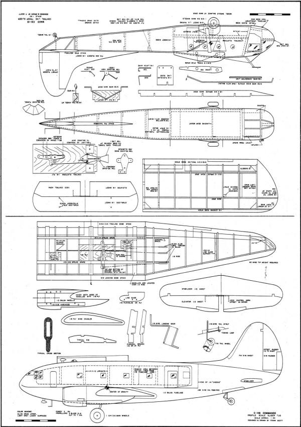
Control Line Troop Glider
and C-46 Tow Plane Plans
Notice:
The AMA Plans Service offers a
full-size version of many of the plans show here at a very reasonable cost. They
will scale the plans any size for you. It is always best to buy printed plans because
my scanner versions often have distortions that can cause parts to fit poorly. Purchasing
plans also help to support the operation of the
Academy of Model Aeronautics - the #1
advocate for model aviation throughout the world. If the AMA no longer has this
plan on file, I will be glad to send you my higher resolution version.
Try my Scale Calculator for
Model Airplane Plans.
Posted October 18, 2014
|


