|
Website visitor Steve R. wrote
requesting that I scan and post this "Square Hare" article from the September 1962 issue of
American Modeler magazine. Says, Steve, "I built one of these back then on Galloping ghost
and it went great till servo failed (modified mighty Midget motor). Later I built
another for Class one Aerobatics fitted with OS 40 and Kraft Propo, this was very
successful. Nostalgia strikes and I'd like to build another as a sport model." Square
Hare from Delaware is a bit unique in that its wing has no spar and is constructed
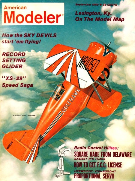
from diagonally arranged ribs sandwiched between 3/32" balsa sheeting. Looking at
all the hardware required just for the elevator control really makes you appreciate
modern radio gear with servos. Hopefully, Steve will grace us with a photo of his
completed Square Hare.
Square Hare from Delaware

Mascot sketch (left) is by Bob Lopshire. Northrop's Square Hare
has been duplicated with great success by many Eastern radionauts of limited experience.
"Square Hare" was first sketched on the back of a specification sheet for a pneumatic
temperature transmitter ... which doesn't prove anything except that we can't all
be like Lincoln and carry envelopes around with us.
Main reason for designing the plane was to carry experiments with the sheeted-wing
type construction beyond the 1/4A Lil Beau Bipe stage.
Idea was to create an R/C model without elaborate plans and using wood sizes
pretty much as they come from the store. Carrying this to the limit, all lines were
squared off as much as possible. Sorta gives a continental look, don't it Henry?

William C. Northrop, Jr. brings you a remarkable radio plane;
grab some sheet balsa and knife!
The first Square Hare equipped with pulse rudder flew right off the drawing board.
(Next one will be built outside, we were lucky the window was open that time.) Weight
came out 44-oz, making loading just a hare under 16-oz per sq. ft. Maiden flight
was without built-in down-thrust shown and Mr. Hare just tilted to about 30°
from horizontal and sort of elevated himself almost straight up without any forward
motion. Just as the engine quit and I was expectantly waiting to check the glide
trim, the rudder came unhooked from the torque rod (I know why, but I won't admit
it even to my best friends). So there I was at 500' with lots of rudder to the left
and absolutely none to the right. Rectangular Rabbit proved how rugged it is by
coming out of the clobber with only a broken nylon prop and Micarta motor plate,
plus a notch in the wing where the leading edge buried itself in the engine cylinder
head fins.
Subsequent tests resulted in reducing decalage to about 1° positive, elimination
of all but a smidgen of right thrust, and fixing downthrust at 5°. These adjustments
are on the plans.
Innards of the rectangular rabbit are viewed.
Sometime later the Galloping-Ghost system was added which brings us to its present
form. Both plane and author have learned a lot about flying since and Hare will
now do spins, snap rolls, slow rolls, loops, 5' off-the-deck buzz jobs, climbing
victory rolls, tail slides (down boy, I've got witnesses) and a few fantastic maneuvers
which cannot be described. It has survived four horrible crack-ups (never mind about
how many were P.E.), all in spite of the fact that it has no fabric covering or
fiberglass.
Probably the most surprising thing about the ship is its wide range of suitability.
I mean in the hands of a rank beginner it has proved to be ideal with respect to
stability, crash resistance, and flying ease. When the experts get on the stick
or start playing with the panic buttons, it suddenly becomes, and has been called,
a Wild Hare. Expert proportional man Vince Bonnema of the NJRCC flew the Hare in
its rudder-only configuration at a DC/RC Symposium and said, "It handles almost
as good as my Rollo." (Brother, thar's a compliment!)
Well, enough boasting, let's get with it.
Construction ... It's always hard to decide how much detail
to go into. Square Hare lends itself nicely to the R/C beginner or even the completely
inexperienced model builder.
Fuselage ... Select two straight, fairly hard 1/8" sheets for
sides. Usually if you take two next to each other in the dealer's rack they will
be from the same log and have the same bending strength and texture. This helps
a great deal in getting that top view alignment. Of course, if some other fussy
modeler was there first, it may take some time to find a matched pair, but it's
worth the trouble.
Lay out body sides on wood using a carpenter's square and soft pencil or ball
point pen. Draw in bulkhead positions. verticals, doublers, motor mount beams. Cut
sides and match them back to back to check accuracy of your position markings. Cut
1/16" plywood doublers using sides as pattern, glue in position. Of course, unless
you're using transparent plywood, this covers up the location of bulkheads A &
B and motor mount beams, which should be re-marked.
Double glue motor mount beams in place, followed by verticals, wing and stab
opening doublers, dowel gussets. Next, very accurately cut cross grain 1/8" sheet
floor that goes under beams and between bulkheads A & B. This floor is the key
to perfect alignment of body sides and corners must be square. Now pour in the Ambroid
and assemble sides, using bulkheads A, B" C-1, C-2, and above mentioned floor, double
gluing all the way. Against fuselage sides, lay pencils long enough to stick out
beyond top and bottom at bulkheads A, B, C and tightly wind rubber bands across
ends. This will firmly clamp assembly together while glue dries.

Designer Bill with his Hare.

Square Hare from Delaware Plans Sheet A

Square Hare from Delaware Plans Sheet B

Square Hare from Delaware Plans Sheet C

Square Hare from Delaware Plans Sheet D
Before glue sets, check alignment once more by making sure that ends meet evenly
when pulled together at tail. If not, twist assembly until tail ends line up without
forcing. Add 3/32 plywood end plate 'D' which keys into notches formed by sides
and 1/8 x 1/2 verticals at tail. Last step before setting fuselage assembly aside
to dry is to insert 1/8 x 1/4 cross pieces at first station behind' 'C'. Cut-and-try
on these until sides, when pulled in to meet them, are just about straight from
station C to D.
When above assembly is dry, 1/8" cross-grain planking can be applied to bottom,
starting at rear and working forward to plywood landing gear insert. It might be
a good idea to bend 1/8" M.W. main gear so it may be positioned and holes drilled
for J-bolts before plywood floor is glued into place.
If you're going to use a Mighty-Midget motor for pulse rudder or Galloping-Ghost,
ply floor also serves as a handy mounting spot for motor, using 4-40 blind nuts
pushed up from the bottom. Double glue ply floor in place, pour in a big cement
fillet on inside where sides meet bottom. While that's setting up, let's get on
with the loop in the 1/8" M.W. nose wheel strut.
I'll explain my method of forming said loop. You'll need a heavy vise, vise-grip
pliers, a steel bar 3/8" in diameter.
The 1/8" M.W. and steel bar are clamped in vise together. M.W. is placed horizontally,
just flush with top of vise jaws, against rear jaw, and with all but about 6" of
wire sticking out to the right. Bar is placed perpendicular to jaws and M.W., against
front jaw, near right end of vise.
Wilmington's Bill Northrop designed this so you work right on the balsa sheets.
Using vise-grips, grab wire an inch beyond bar, holding vise-grips as near parallel
to wire as possible; slowly and carefully pull wire around bar. Wire must just clear
top of vise. After a 1/4 turn, vise-grips will pull up against bar and you must
release wire, slide back an inch, grab again and continue pulling around. Watch
carefully where wire is clamped in vise to make sure it's not going to pop out.
You wind about a turn and a quarter to get one complete loop since wire tends to
open up a little, which is also why you must use a steel bar smaller in diameter
than loop you want. Don't give up on the first try. I loused up about 4 or 5 before
I got a good one.
Assuming you got through that okay, bend rest of nose strut and install on bulkhead
A with 3 J-bolts. Finish planking bottom using 1/8 balsa and ply as shown. Fill
space below engine beams in front of bulkhead A with balsa block for additional
strength and to eliminate a fuel pocket.
Install control system before closing top of body. If escapement, reduce rudder
width to 1" and put in 1/4" movement to each side. You can leave it as is if you
want, but an escapement version using rudder shown with 3/8" movement stands right
up on a wingtip when button is pushed. Some G.G. installation suggestions are given
on the drawing, later in text. Complete body by adding 1/8 x 3/8 wing rest pieces,
forward 1/8" M.W. wing hook held with J-bolts, 1/4 balsa stiffener and filler B-1.
Empennage ... Construction of rudder and stabilizer needs no
description. Don't leave out wire reinforcement for rudder bands or 1/4" diagonal
fillets between fin and stab. Empennage may be glued on, but evidence proves detachable
one will last longer.
Wing ... Although wing construction is unique to R/C, it is
certainly nothing new. For a slight increase in weight, it provides a sturdy and
quickly-built structure which is impossible to warp. For this reason a certain amount
of care must be observed during construction. If wing is built out of line it will
remain that way.
Start construction by butt-gluing two pieces of 3/32 x 4 medium soft balsa together
for each top surface panel. It's best to trim joining edges with metal straight
edge before gluing. Of course, you may be able to find four equal grained pieces
with well matched edges at your hobby shop if you look long enough (your dealer's
going to love you when you get through with this one). Pin joined surface to flat
surface. While you're at it you might as well butt glue 1/16 bottom planking, too.
Prepare leading edges by beveling 1/2 x 3/4 hard balsa as shown. Best done on a
table saw, this can be planed down by hand. Next, glue leading and trailing edges
to underside of top panels being sure to cut 1" taper in tip first and making certain
you end up with one left and one right hand panel.
Cut all ribs using aluminum templates made from full size patterns. One last
step before actual assembly ... give underside of wing panels two coats of dope.
When you are ready to start, take phone off hook and lock yourself in your room.
This is one job you can't stop in the middle. Wet top surface of one panel with
water. Shortly, wing will try to make itself into a tube. Fit, glue into place,
and pin, from the top, all ribs for one panel. Shorten tip ribs to fit but don't
trim them to fair into trailing edge now. Leave out center rib. Pin whole structure
to flat surface to dry. Repeat with other panel.
Purpose of not tapering tip ribs is to keep top surface of wing absolutely flat
while drying. Later, when bottoms of these ribs are tapered up to meet trailing
edge you will automatically have that important washout built into the wing tips.
This also should explain why you cannot build wing by starting with bottom sheet
and working up.
When the panels are dry (give them 12 hours at least) and removed from the flat
surface, try an experimental twist and you'll see what I mean about warp-proof.
Now block each panel tip up 3 inches, sand in the dihedral bevel at the center (hand
launch glider style), and double-glue the two panels together. Add the 1/8" plywood
dihedral gussets and the center rib which has been shortened 1/8" at each end. Finally,
trim those tip ribs as mentioned before, then plank bottom with previously prepared
1/16 sheet. After shaping, sanding, filling and/or clear doping, and before covering
(if used) wrap 3" band of Celastic or fiberglass around center section.
Finish ... the original Hare was given three coats of filler
made by adding talcum powder to thinned dope. This was followed by the trim color
(a metallic copper, made from orange and silver with a dash of yellow) and two coats
of clear. All butyrate. No silk or nylon covering was used, although there's no
denying Rugged Rabbit would be stronger for it, albeit heavier.
If you want the S.H. insignia on the wing, trace and transfer it to the wing
with carbon paper; use a glass-marking pencil (such as Stabilo) to finish the job.
Protect with clear dope.
Special Notes on Galloping Ghost R/C Installation
G.G. installation ... The small amount of down in relation to
up elevator requires fast pulsing to get level fight. This almost completely eliminates
gallop even in full up.
Bind with string or glue with Walther's Goo the M.M. motor brushes to motor body.
Engine vibration will loosen these eventually. Don't wait until you develop a 50'
outside loop from 25' to follow this suggestion. Don't forget the .01 condenser
across the M.M. brush contacts. Glue this to the floor with contact cement to prevent
vibration from fatiguing the leads.
Install hardwood bearing halfway between M.M. and tail-plate D to prevent whipping
and subsequent vibration-binding of torque rod. A 3/32" bearing hole is big enough
to restrict whipping without creating a bind.
If you're a newcomer to G.G., adjust Center of Gravity 3/8" ahead of where shown
to tame-down the Hare's reactions to stick movement. When you are ready to shoot
the works, add weight to the tail until Center of Gravity is as shown or even back
another 1/4". The Hare will do a 2-1/2 turn snap roll followed by a spin if you
snap the stick back first and then hit a panic button (full-off or full-on).
Notice:
The AMA Plans Service offers a
full-size version of many of the plans show here at a very reasonable cost. They
will scale the plans any size for you. It is always best to buy printed plans because
my scanner versions often have distortions that can cause parts to fit poorly. Purchasing
plans also help to support the operation of the
Academy of Model Aeronautics - the #1
advocate for model aviation throughout the world. If the AMA no longer has this
plan on file, I will be glad to send you my higher resolution version.
Try my Scale Calculator for
Model Airplane Plans.
Posted September 20, 2024
(updated from original
post on 1/4/2016)
|