|
This article and plans for the Ole Tiger quarter midget
racer were scanned from my purchased copy of the August 1973 American Aircraft Modeler magazine. Plans
for this fine model were drawn by Mr. Don Panek. All copyrights (if any) are hereby acknowledged.
OLE TIGER
Q-Midgets are fun for Racing, Sport flying, and Stand-off Scale. Ole Tiger features the House of Balsa
wing for quick and true construction.by Don Panek Having the desire to race and compete
is an instinct born in every individual and almost every modeler who has ever watched Formula I or FAI
contest. I personally started with an interest in Formula I, but as the years passed by, the event overwhelmed
me due to the great amount of time and money required to compete on a near or equal basis. Recently,
the Quarter Midget event has come into its own, and with it a chance for everyone to compete in a racing
event without the necessity of devoting all of his resources to only one phase of this great hobby.
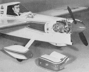
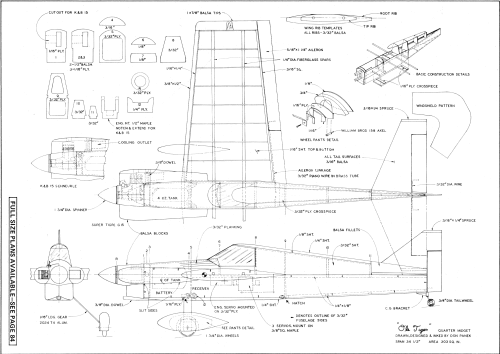
 The ST-powered version is the original model. A K&B Schnuerle version is shown
on the plans. Remember, Q-Midgets must have a stable engine idle, so you can land under power if desired.
Club contest schedules are now including the Quarter Midget event across the country and if you're looking
for a model capable of competing successfully, plus a sleek appearance, "Ole Tiger" is for you.
The design meets all existing rules plus those presented to the AMA contest board, which were outlined
at the Toledo (Ohio) Quarter Midget meeting in February. Construction has been simplified by
using a unique wing design concept utilizing two fiberglass arrow shafts for both structural strength
and as the wing building jig. The credit for this concept goes to Don Dombrowski, owner of the House
of Balsa, 2814 E. 56th Way, Long Beach, Calif. 90805, who offers the wing kit, complete with shafts,
sheeting, die-cut ribs and formed wire aileron linkage for $11.95. Construction
I personally like to cut all parts out prior to beginning a project. Once completed,
the fun of assembling begins. The wing ribs are made by stacking nine pieces of 3/32" balsa cut to lengths
noted on plans, placing them between a root and tip 1/16" plywood rib template. Drill the two 1/4" dia.
holes, bolt the stack together and sand to shape. Repeat for the other side of the wing by reversing
the tip and root template. Be sure to mark ribs with a felt tip or ball point pen to denote top and
front to avoid confusion during assembly.
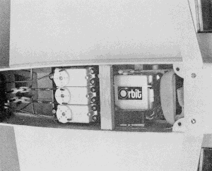
 All equipment access is through the bell hatch; it is a one-piece plane. Use those
servo trays they provide the best vibration and crash protection.
Two engine installations are shown, one for the Supertigre 15, and the other for the new K&B 15
rear rotor. If you plan to use the K&B 15, cut the engine mount to the longer configuration and
notch out the section noted to clear the rear of the engine case. At this time, drill mounting
holes, using plans for proper placement of engine. Sheet metal screws or blind nuts can be used to hold
engine in place. The firewall assembly, consisting of bulkheads 1, 2 and 3, is cut out to
the shape noted. Epoxy together with the engine mount in place. The mount will align the assembly, but
make sure mount is at right angles to firewall surface, to assure a zero thrust line. When a
K&B 15 is used, it will be necessary to cut out section noted on plan in dotted lines after the
assembly has cured. Sand assembly to contour shown on top view. The basic fuselage sides are
cut out to outline shown, stacked together, sanded true and the two 1/4 dia. holes are drilled. Cut
slit in forward section as noted. Glue the 1/4 x 1/8" strips to upper and lower edge of the basic fuselage
sides. The upper strip ends just aft of bulkhead 5 and the lower one ends aft of bulkhead 9.
Sand rear of sides to angles shown and glue together with bulkhead 9 in place. After curing, epoxy
firewall assembly in place, align assembly using top view and clamp sides. Glue bulkhead 4 to 5. Place
assembly on a flat surface, bottom side down and proceed to epoxy the landing gear, hatch mount and
3/32" plywood aft hatch cross cross piece 1/16" off the building surface. Next, epoxy the assembled
bulk-heads 4 and 5 to fuselage sides and mount 12. The remaining bulkheads and bottom 1/4 x 1/8" cross
pieces are now glued in place. The 1/8" sheet top turtle deck (cut to inside dotted lines) is glued
in place and sanded flush with bulkheads. The upper nose section from 1 back to 8 is now planked
with 3/32" strips. Cut strips from a sheet in varying widths to meet your needs. The 3/32" sheet sides
of the turtle back are now glued in place, and the assembly is left to dry. The inside of the nose section,
forward of bulkhead 5, is now coated with epoxy and glass cloth. The upper 1/4" sheet turtle deck cap
is now glued in place. The rear balsa fillets are formed by tack gluing two blocks to two 3/16" sheet
spacers which take the place of the fin and stabilizer. This assembly is tack glued in place and left
to dry. Rough sand planked area, rear of fuselage and fillet blocks, being careful not to round off
edges where front cowl blocks are to be placed. At this point the wing assembly begins with
the two 1/4" dia. fiberglass shafts cut to 32-1/2" length. Shafts can be obtained from sporting goods
outlets or plastic supply houses in various lengths. Mark the locations of ribs and centerline on the
shafts using a pencil or marking pen. Slide shafts in fuselage and place bottom of fuselage on a flat,
true surface. Using two 2-1/4 x 6" (preferably 1/4" thick) sheet spacers, place under outer tips of
the shafts. If shafts are out of line and do not lay flat on the spacers, enlarge holes slightly in
fuselage sides until they lay flat and true without force being applied. Apply epoxy to shafts from
inside of fuselage and let assembly completely cure. Next, slide down ribs in proper sequence
being sure that the top and front of the rib is correctly located. Lay a straightedge against the leading
and trailing rib edges to assure proper location. Epoxy root rib to fuselage side, pin or tape to side
of fuselage to maintain contour, and wipe excess epoxy from edges of rib. Next, apply slow-curing
epoxy to remaining ribs. To insure a true wing, rotate tip ribs back and forth until whole assembly
will lay flat on spacers, without external pressure. Allow to completely cure. Glue 1/16 x 1/4"
front edge and 3/8" square rear edge in place. After it is dry, sand edges to meet contour of ribs.
The two wing skins, each consisting of three sheets of 1/16 x 3 x 36" medium balsa joined together
with Francis resin, are now prepared. This isn't a difficult task if you select the sheets from a common
bundle at the hobby shop, making sure the edges are not bowed or unusually rough. Match the sheet edges,
sand as necessary for a good fit, and apply the resin to the edge with a pipe cleaner. Pin the sheets
down on a flat surface covered with waxed paper and let cure. Sand both the top and bottom surfaces
using a 280 grit The skin is now glued in place over the ribs and butted against the fuselage
sides. Lay a straight piece of hard balsa on the front and rear edge of the shim, and use large clothespins
to clamp in place. Remember that this whole process must take place with the two wing templates supporting
the underside of the fiberglass spars to insure a true wing. After curing, remove the clothespins and
apply the lower wing skins. At this stage, the wing assembly is rigid and only requires clamping in
place during drying. Sand the front, trailing edge and tip flush and glue the 3/8 x 1/2" leading
edge in place. The trailing edge stock is now cut as shown. Route out the inboard section to receive
the aileron torque tube assembly and, using five-minute epoxy, glue tube and trailing edge in place.
Be sure not to get epoxy into torque tube during this assembly step. Next, glue tips in place
and apply ailerons to wings. I don't specify hinges because of the numerous types available, and each
of us has his own preference, My only comment is to use enough to assure a strong assembly.
With the wing completed, we will now proceed to finish the fuselage. Epoxy a 1/16 x 1/4" plywood strip
to the bottom and forward edge of the landing gear mount (12). Next, position formed landing gear on
mount and drill two holes for 4-40 screws. Once drilled, place two 4-40 blind nuts on inside and screw
down into mount. Glue the forward bottom 1/4" sheet in place. This sheet extends from bulkhead (1) to
the leading edge of the landing gear opening. Make hatch cover from 1/4" sheet and epoxy the
two 1/16" plywood cross pieces as shown. Drill the three holes in mount and rear 3/32" cross piece and
install 4-40 blind nuts. Undercut hatch to clear the two screw heads holding the gear in place and countersink
hatch. Hold down screw openings. Fit nose blocks around engine mount and epoxy left cheek cowl in place.
With engine mounted, make right cheek cowl from I" thick balsa, route out section around engine, and
extend to cooling opening. After fitting block, glue 3/8" sheet to complete cowl. After rough assembly
is complete, epoxy nose ring R in place, leaving approximately 1/32" clearance between ring and nose
spinner. Cut cowl aft of area assigned for 3/8" dia. dowel support. (Location noted for K&B 15 or
Supertigre.) Epoxy dowel and rear of cowl assembly in place. Epoxy a 1/16" plywood piece inside
removable cowl section where it butts against the dowel. Trim dowel so cowl fits flush. Drill hole through
cowl into dowel and fasten with sheet metal screw: Fill in areas around wing and cowl with a mixture
of micro balloons and Francis resin to form fillets, and completely sand assembly to contours shown.
Make tail surfaces from 3/16" medium grade sheet balsa and don't forget to use the spruce tips-these
prevent warpage and insure against damage. Re-move formed tail fillet assembly from fuselage and break
away the two side fillets. Epoxy the hinged tail surfaces, tail-wheel bracket and fillets in place.
Make pants per detail sketch; shape and sand to finished contour. Install radio as noted, engine
servo on plywood plate and three servos mounted on tray or directly to two 3/8" square maple cross pieces.
After installation of pushrods, horns, etc., glue bottom of fuselage in place. I prefer leaving the
bottom off to the last, to assure myself that the rods are free and not touching. Each of has
a preferred method of finishing. I used two coats of Francis resin sanded to a smooth finish and two
overall coats of Hobbypoxy white sprayed on with an air brush. The trim is red Hobbypoxy and blue Mylar
tape for pin striping. The shield and racing numbers were cut from standard MonoKote. The emblems on
the side of the fuselage, Bardahl, Champion etc., were purchased from the House of Balsa. They are Mylar
film with adhesive backing and are designed to take hot fuels and meet the scale size required. The
tiger decal was made by spraying clear dope on the adhesive side of brown paper tape, hand painting
the tiger and words, and then applying by soaking in warm water. Full details and photos of
the real aircraft can be found in Volumes IV and VII of Racing Planes (Aero Publishing).
Flying Check all controls and be sure balance point is as shown on plans. The
surface movements should be as follows: Ailerons-3/16" up and down; elevator-3/16" up and down; rudder-3/8"
right and left. Have your helper hold aircraft, rev up engine and hold a little right rudder
and a slight degree of up elevator. Upon release, and when model is tracking true, release right rudder
and up elevator, until enough speed is reached for takeoff. The airfoil used in this model will allow
you to turn as tight as possible without snapping, with very little drag at high speed, and still allow
landings to be made at a very slow speed without fear of stalling. If so inclined, this is a great sport
model and with a few added details it could do well in Stand-off Scale.
 <click image for larger version>
Notice:
The AMA Plans Service offers a
full-size version of many of the plans show here at a very reasonable cost. They
will scale the plans any size for you. It is always best to buy printed plans because
my scanner versions often have distortions that can cause parts to fit poorly. Purchasing
plans also help to support the operation of the
Academy of Model Aeronautics - the #1
advocate for model aviation throughout the world. If the AMA no longer has this
plan on file, I will be glad to send you my higher resolution version.
Try my Scale Calculator for
Model Airplane Plans.
Posted July 14, 2010
|