|
The Eclipse is a gigantic radio-controlled sailplane model with a 16-foot wingspan,
geodesic ribs construction, and "V" tail configuration. It is built up from
balsa, plywood, spruce, and a fiberglass tail boom. I remember first seeing
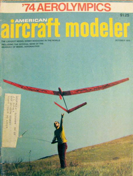
the model on the cover of the October 1974 issue of American Aircraft Modeler
magazine and really wanting to build one. Unfortunately, I was only 16
years old at the time and was barely able to afford control line models, let
alone a huge RC sailplane. Of course with the cost of balsa today, it is no more
affordable now as then. It probably takes four rolls of Monokote to cover! Here
are plans for the Eclipse that I electronically scanned from my
purchased copy AAM. You might be able to scale up the image below
if you cannot find a source for ordering plans, because they do not seem to be
in the AMA Plans Service
inventory. Plans for this fine model were drawn
by Mr. Hal Cover. All copyrights (if any) are hereby acknowledged.
Eclipse R/C Sailplane
 It casts a big shadow - with 16 feet of wing it should! Designed specifically
for extended duration, the Eclipse will ride thermals almost forever. It casts a big shadow - with 16 feet of wing it should! Designed specifically
for extended duration, the Eclipse will ride thermals almost forever.
By Hal Cover
Why a glider with a 180" span and the name Eclipse?
You will understand the first time it flies over your head with its gracefulness
and beauty. When it lands the size becomes very apparent, and you might even expect
a pilot to climb out looking for his glider trailer.
In comparing the performance of the Eclipse to a smaller version, interesting
performance variations appeared. First it flew in much higher winds than the smaller
one, even thought both had a an 8 oz./sq. ft. wing loading. Also, still air flight
times were as much as 50% better with the larger model. Probably the larger glider's
only weakness is that it is hard to pick up thermals at low altitude. The relatively
large tail and long tail moment contributes to its extremely stable flight characteristics.
In calm weather, flights of up to ten minutes have been made without aid of the
controls - in other words, free flight ... that includes the launch, too! If the
plane is allowed to fly straight, it will turn into lift by itself and stay in lift;
so let it find the lift for you. The spoilers are just effective enough to allow
a good controlled sink, with only up trim needed for proper attitude. This makes
spot landings a cinch.
The spoilers proved their worth on one flight where the plane rode a thermal
until it disappeared in the clouds. At this point, the spoilers were opened and
a large circle set in the controls. Without further action, the plane came down
safely ... but it took half an hour! This plane is big, and therefore can't be treated
like a small plywood and foam glider. If it gets way up in a thermal, use the spoilers
and up trim; don't dive it or spiral it in because the plane picks up speed fast
and it is not indestructible.
Locating a fiberglass tail boom for the Eclipse may pose a problem for prospective
builders. However, there are several approaches one can take. First, as the author
did, contact your local sporting goods store and have them recommend a fishing pole
manufacturer from whom you can make a selection.
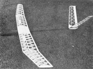 The
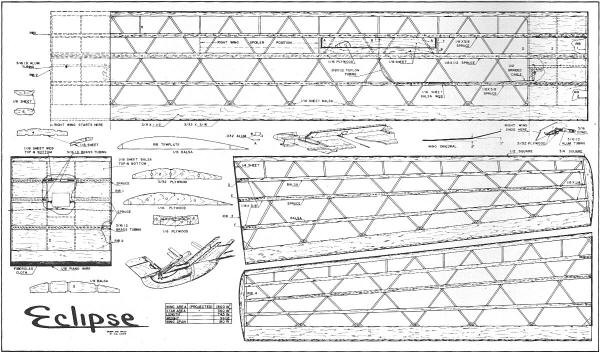
Eclipse is not, as it looks, a myriad of little pieces - it's a myriad of big pieces!
Using geodetic construction is the only way to build a 16-foot soarer with a reasonable
wing loading and good strength.
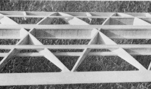
Detail shot of the wing structure shows spar webbing and warren truss ribs.
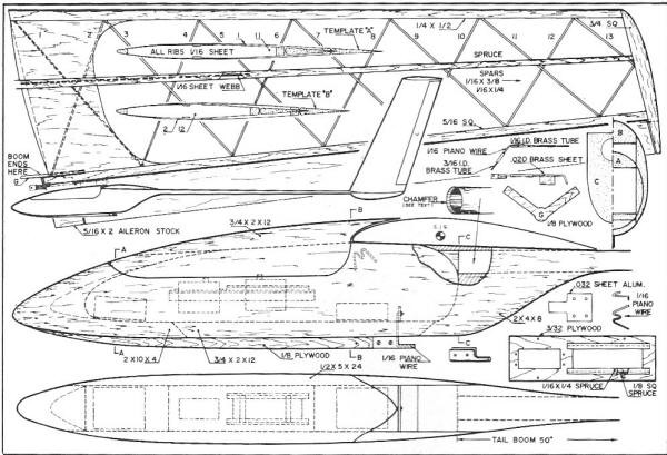
The modular wing center section houses the spoiler servo. The model disassembles
very quickly and stores easily with this arrangement.
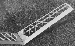
The V-tail is ultra-light, yet rugged. Minimizing drag on a 50" tail moment is
critical to maneuverability.
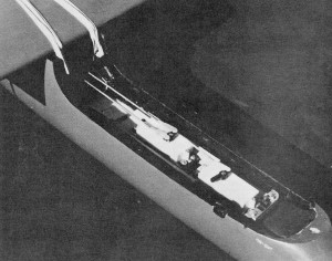
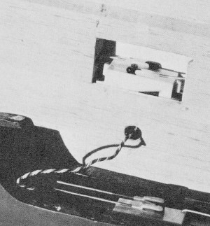
The back servo slides on a tray. The link to the forward servo is drilled right
into the servo case top. The slender pod decreases drag.
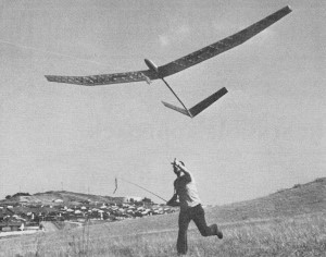
The author launches the mammoth beastie. The light wing loading makes hi-starts
practical.
If no manufacturer is readily available, perhaps the sporting goods store will
order one for you. The fiberglass rod should be about seven-nine ounces in weight,
eight to nine feet long and have a diameter of approximately 1 1/4" at the large
end. If you have difficulty with either of these approaches, contact me, c/o AAM,
and I'll supply you with a boom equivalent to the one used on the original Eclipse.
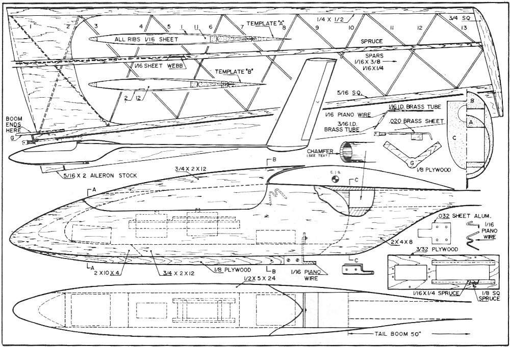
CONSTRUCTION
Building Tips: Always use spruce wherever shown - don't substitute
balsa. Web all areas indicated with hard balsa. The wing and stab structures require
a web for necessary structural properties.
The wing center section needs the 1/16" piano wire and fiberglass cloth covering
on the trailing edge; it is also recommended that the center section leading edge
and tip dihedral leading edge and trailing edge joints be fiberglassed. Use epoxy
and glass cloth as needed wherever wire hooks or tubing are installed.
Fuselage Construction: The fuselage is constructed from medium
balsa sheet and blocks. The sides are cut from 3/4 x 5 x 24" sheet, the nose block
is 9 x 2 x 4" and the rear fuse block is 5 x 2 x 8". 3/4 x 2 x 12" sheet is used
on the top and bottom. The tail boom size may vary depending upon what is available,
but the author's plane had a boom 50" long, 1" in diameter tapered to 1/2" diameter.
Cut out the blocks as shown on the plans. Glue the blocks, top and bottom sheet
to a side sheet. When dry, sand the edge of the unplanked side to obtain a good
flush joint. Glue the second side in place. Don't carve the fuselage to the correct
cross section until the tail boom is installed.
Tailboom Installation: The tail boom installation is critical
and should be done carefully. Place the fuselage upside down on a flat surface at
least six feet long. Block up the wing mount platform to the correct incidence angle,
as follows: The leading edge portion of the wing platform (at former B) should be
1" off the bench, and the trailing edge should be 1-9/16" off the bench. This will
position the wing platform on the fuselage at the correct incidence angle, with
the bench surface representing 0°.
In the next operation, the tailboom is going to be used as a drill. Carefully
sharpen the large end by chamfering the inside, as shown on the plans. Alignment
of the boom is achieved by blocking the small end of the boom to the same height
(1-9/16") above the table as the trailing edge portion of the fuselage-the boom
is now at 0° also. A straight line drawn on the bench may be used for boom alignment
left to right. With the fuselage and boom held in the proper position on the locating
blocks, push the boom into the block and drill by rotating with a fair amount of
pressure. Once the boom is into the block about one inch, the assembly may be removed
from the bench to finish the boring operation. This method may seem a bit strange,
but it gives an accurately aligned and tight fitting boom. Remove the boom from
the fuselage, take the plug out of the boom and reinstall with five-minute epoxy.
Carve the fuselage, using the templates shown for correct contour. Then cut out
the cockpit with a band saw or coping saw.
Cut the plywood skid from 1/8" plywood and bond to the fuselage. With the canopy
in place, cover the entire fuselage with one layer of one-ounce glass cloth. Put
an additional two layers on the nose and bottom of the fuselage, including the skid.
Remove the canopy and grind out the nose block as shown with a Moto-Tool or similar
device. The canopy can be held in place using several methods. The original was
held with a locating dowel in the front and snaps in the rear.
Servo Installation: The servo tray is made from 3/32" plywood.
The servo cutout size will depend on the servos used. The sliding servo is mounted
to two pieces of 3/32" plywood: 1/4" x servo width, plus 1/4". The guides for the
sliding servo are made by cementing 3/32" sq. hardwood to the strip on both sides,
1/8" away from the servo cutout. Glue a strip of 1/16 x 3/16" hardwood on top, with
the overlap to the servo side. When cementing this assembly, make sure the sliding
servo can move freely up and down the tray slide.
Towhook Installation: The towhook is made from soft .032 aluminum
and 1/16" wire. Bend the wire to shape and cut out the 1/4 x 2 x 5/8" plywood support.
Place the piano wire in the fuselage as shown. Slip the aluminum hook in place and
bolt to the skid using 4-40 bolts.
Wing Hook Installation: These are formed from 1/16" piano wire
and epoxied to the side of the fuselage, as shown. For additional strength, cover
them with two layers of glass cloth and epoxy.
Do as much finishing work as possible on the fuselage prior to stab installation,
because of the sheer size and awkwardness of the fuselage/stab assembly.
Stab Construction: Only half the stab is shown on the plans
but, since the airfoil is symmetrical, build two halves on the plan and flip one
over for the other half.
Using blocks, pin the leading edge and trailing edge in place 1/4" above the
plans at the center and 1/8" above at the tip. Cut out the ribs using the template
shown. Note that half of the ribs are solid, or uncut, and zigzag to the tips. These
should be installed first, followed by the installation of the cut ribs.
The method of obtaining the correct airfoil for all ribs is done as follows.
Mark the 1/16" sheet balsa with the required rib length and the 1/4" leading edge
and 5/16" trailing edge height. Use airfoil template "A" for the odd numbered ribs
1, 3, 5, etc., and template "B" for even numbered ribs. Lay the airfoil template
on the sheet balsa with its leading edge placed so that the top mark just shows.
Position the rear of the template in a similar manner, with the trailing edge mark
just showing, then cut the top airfoil. Repeat the operation for· the bottom surface.
Spar Installation: The tapered spruce stabilizer spars are installed
by marking the spar location and width (mark both sides) on the inner rib (1) and
the tip rib (13). Next lay an aluminum yardstick or straightedge over the front
marks, and cut a notch 1/16" deep in all ribs. Move the yardstick to the back marks
and notch again. Then cut out the material between the notches.
Turn over and repeat the operation on the bottom of the stab. Add the tip block
and glue the spruce spars in place, but make sure there are one or two inches extra
in the center for stab installation to the tail boom. Shape the LE and TE, then
sand all ribs.
Stab Installation: Fit the leading and trailing edge to the
boom carefully. Epoxy the dihedral brace (G) to the end of the boom, making sure
it aligns with the wing platform. The spars will lay over and under, as shown on
the plans, and should be butt jointed. When all items fit correctly, epoxy the stab
halves to the boom again making sure it aligns with the wing platform. The hinge
mechanism is bent to shape using 1/16" piano wire and 1/16" ID brass tubing. The
lower portion of the hinge or clevis attachment is made from 1/8" ID brass tubing
soldered to the wire and flattened. Drill a hole into the brass for the clevis.
The brass tubing portion of the hinge is epoxied to the rear spar. The fixed
portion of the 5/16 x 2" trailing edge is notched to fit over the tubing and wire.
The elevons can now be fitted and sanded, but not permanently attached (5/16 x 2"
light aileron stock works well for the elevons, if available).
Web and stab spars using hard 1/16" sheet with the grain vertical (the web should
run to half span), then sheet the top and bottom center section.
Push rods: Carve out the push rod holes as shown, and fabricate
the push-rods from 1/4" hard balsa 48" long, with threaded clevis wire on both ends.
The wire length is determined by the servo installation and hinge connection hole
location. When the linkage is installed and working, one should get ± 40° travel
out of each surface.
Tail Skid: Two 1/2 x 10 x 2" blocks can be cut to the shape
you desire. These are then hollowed out for both linkage clearance and weight. Next,
they are carefully fitted to the tailboom and glued in place. After final sanding,
the tail skid should be covered with a layer of fiberglass cloth and resin.
Wing Construction-Inner Panels: The 28 inner panel wing ribs
are cut from medium 1/8" sheet, using the diagonal rib template. The false ribs
(5) are also cut from the same medium 1/8" sheet. All inner panel spars are spruce,
with 1/8 x 1/2" used for the center spar, and 1/8 x 3/8" used for the front and
back spars. Medium hard balsa wood should be selected for the leading edge and trailing
edge. Before the wing is constructed, add 3/32 x 3/16" spruce to the back of the
trailing edge. This strip is very effective protection against dings and cuts when
building and flying.
Cut two number 3 ribs from 1/8" hard sheet balsa. Do not cut the ribs apart at
each spar location until the spar has been installed in. a later building step.
Pin the LE and TE down over the plans. Block up the plywood ribs 1/16" when installing
to allow for the bottom sheet. Glue the geodetic ribs in place, noting which are
continuous and which are cut in half when forming the geodetic structure. When the
basic structure is dry, remove from the plans and build other inner panel in a similar
manner.
Wing Tips: The tips are built using medium balsa for the LE
and TE, and medium hard balsa for the front and back spars. The center spar is cut
from 1/8 x 3/8" spruce.
Cut the wing tip ribs out of light 1/8" sheet balsa using the diagonal rib template.
Use the same procedure for these ribs as used on the stabilizer ribs. Some ribs
will be slightly thicker than necessary and must be sanded to the correct contour
after the spars have been installed. The actual construction of the tips is done
in the same manner as the inner panels.
Wing Dihedral: Pin or weight the inner panel down to the bench
and block the tips up with 7" of dihedral. Sand carefully to fit, then glue together.
Add rib 3 (still not cut apart). When dry, remove from the bench and carefully mark
the spar locations on the tip rib 4. To notch out for the inner panel spars, lay
an aluminum straightedge over the ribs, using the plywood rib notches and dihedral
rib 3 notches for position reference. Cut a 1/8" deep notch in each rib-repeat this
step until all spars are notched at both the front and back edges. Trim out all
notches to 1/8" deep. Notch the tip ribs in a similar manner, except use the marks
on rib 4, and the notches of rib 3 for spar location reference.
The spars should be glued in place 1/16" above the plywood ribs to allow for
sheeting and be flush with all balsa ribs. Add the lower spars first. Cut out the
spaces between rib 3 sections so that the 1/8" plywood dihedral braces D, E and
F, can be installed. Next add the upper spars. When the spars are added to the tips
you will find that some ribs are too high. These should be notched deep enough to
allow the spars to be flush with the top of the lower or thinner ribs. Use a straightedge
on top of the spars to make sure it is flat and not irregular due to incorrect spar
notch depth. The center spar is webbed with hard 1/16" sheet balsa out to the center
of the tips. The front and rear spars are webbed to the tip dihedral break. The
grain of the web must run vertically if it is to be effective.
Spoilers: Laminate two pieces of 1 x 12 x 1/6" plywood to two
pieces of soft 1/8 x 1 x 12" sheet balsa. Epoxy the hinges and horn to the plywood.
Add the 3/16" ID aluminum tubing to the center ribs (2) and glue the 3/32" plywood
bellcrank and mount in position. Set the spoiler in place and epoxy the hinge to
rib 6, then glue rib 7 in place. Rib 7 acts as a stop, to locate the spoiler in
the proper position when closed. Sand the upper surface of the spoiler (1/8" sheet)
to match the upper airfoil contour. Epoxy the Teflon or vinyl tubing in place as
shown. Slide the 0.012 braided cable through the tubing and attach it to the spoiler
horn and bellcrank. Then add a light tension spring to the spoiler, as shown, to
hold the spoiler closed.
The action for opening the spoiler is quite simple. The servo, mounted on its
side in the center section, pushes two rods out, which press against one end of
a 3/16" dowel located inside the aluminum tubing of the inner wing panels. The dowel
pushes against the bell crank, which pulls on the cable and opens the spoiler. This
system requires no actual center section-to-wing hookup. The worst problem that
can occur in flight is, if the wings slide out on the rods a bit, the spoilers will
only partially open when activated.
Wing Center Section: Slide four of the number 2 ribs on four
brass tubes cut to the correct length (the center tube is two pieces, to allow for
the servo mounting in the middle). Place on the plan and block up 1/16" to allow
for sheeting. Coat all rib ends with glue and place the LE and TE in position. Hold
them in place with pins or weights. When dry, remove from the plans and add all
the spruce spars. Web the spars with 1/16" hard wood or plywood. Next install the
servo and drill holes in each rib to allow the clevis rod to pass through and mate
with the inner panel aluminum tubing/spoiler assembly. The entire top and bottom
is sheeted with firm 1/16" sheet with only a cutout in the bottom sheet for servo
access.
Wing Assembly: Position the brass tubes into the inner wing
panels. Check alignment with the center section tubes. If all aligns, epoxy the
tubes in place. Block off the end of each tube with a 1/2 x1" piece of plywood,
so that the tubing cannot be pushed into the wing. The tubes should then be webbed
top and bottom with 1/16" spruce or plywood.
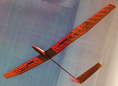
A beautiful study in sailplane aesthetics, the Eclipse is elegant and spirited
in flight.
Assemble the wing, using six rods of piano wire 3/16" dia. approximately 7" long.
Check out the spoiler mechanism and, if all works well, sheet the top and bottom
of the inner panels with firm 1/16" sheet. Shape the leading edge and ribs to remove
any burrs or rough spots on the wing surfaces.
Covering: The covering is accomplished with the help of the
Bank of America and four rolls of MonoKote. All surfaces are covered with normal
MonoKote procedures. Cover movable surfaces before installation. The original Eclipse
was covered with red MonoKote on the top surfaces and orange MonoKote on the bottom.
Chrome mylar trim is used on the leading edge for visibility and directional reference.
You will be surprised how effective these strips are when the plane is a dot in
the sky - and with this plane, that's high!
Flying: Balance the plane to obtain a flat, straight glide with
all trim adjustments set in neutral. Use the CG shown on the plans for a reference.
Balance may take as much as 12 ounces of lead, depending on your construction weight
and RC gear.
With this flight setup, you will find full right or left trim, along with full
up trim, will give you a nice circle for hands-off thermal soaring.
Good luck with your Eclipse and, if you have half as much pleasure from your
plane as I have, you will agree that the work building it was well worth it.
<click
for larger version>
<click
for larger version>
Notice:
The AMA Plans Service offers a
full-size version of many of the plans show here at a very reasonable cost. They
will scale the plans any size for you. It is always best to buy printed plans because
my scanner versions often have distortions that can cause parts to fit poorly. Purchasing
plans also help to support the operation of the
Academy of Model Aeronautics - the #1
advocate for model aviation throughout the world. If the AMA no longer has this
plan on file, I will be glad to send you my higher resolution version.
Try my Scale Calculator for
Model Airplane Plans.
Posted August 14, 2024
(updated from original
post on 3/18/2012)
|