|
Here is another sailplane that,
like the Aquila, really appealed to me back
when I first saw it in the August 1974 edition of American Aircraft Modeler
magazine. The
Astro-Jeff's 12'-7" (151") wingspan and 1370 sq. in. of wing area, was too much
for my 16-year-old wallet. The cost to build and cover it, and then the launch system
needed was way more than what I was accustomed to paying compared to my Standard Hi-Start
and 72" and 99" gliders (the 2-meter class hadn't been created yet).
I had forgotten about the
Astro-Jeff until a
few years ago when I ran across a re-kitting of it by Mr. Jim Ealy of
Vintage Sailplaner. He offers a short
and full kit of the Astro-Jeff
with a fiberglass fuselage.
Maybe now that I have a lot more money (don't I wish), someday I probably will
finally build one of my own.
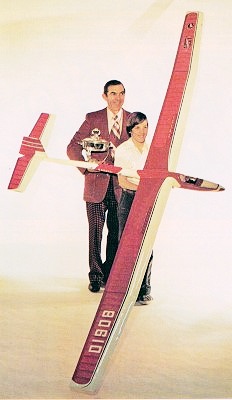
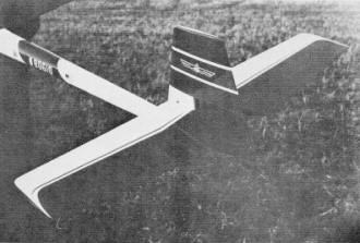
Astro-Jeff
Grand Champion of the 1973 SOAR NATS, this soarer has set a standard of excellence
for sailplanes. It's rated among the top RC glider designs of all times.by Jerry
Mrlik
The Astro-Jeff
is the result of an attempt to design an attractive looking, large RC sailplane
which would have good thermal qualities, long range, good maneuverability, and a
device to aid its pilot in making successful landings. Larger sailplanes seem to
be scoring better and, as the soaring sport progresses, more fliers are using the
big gliders to obtain the higher levels in LSF.
 A great deal of thought and effort
have gone into the design of the
Astro-Jeff. Primary
consideration was given to strength versus weight, and every attempt was made to
optimize the usual design compromises. A great deal of thought and effort
have gone into the design of the
Astro-Jeff. Primary
consideration was given to strength versus weight, and every attempt was made to
optimize the usual design compromises.
The biggest question was what to use for wing wires in a sailplane having close
to 1400 sq. inches of wing area. Having witnessed numerous large sailplanes fold
their wings on the tow, while using 125-lb. test line, I decided to design a wing
system that would exceed the tow line requirements. Making the necessary strength
calculations, I decided on the 1/16 x 5/8" spring steel cross section. The advantages
are several (greater strength with less weight): (A) The modulus of this section
is the equivalent of using six pieces of 3/16" diameter music wire; (8) The weight
savings are in ounces; (C) The spring steel blade, when used on edge, has the flexibility
in the fore and aft direction equivalent to one piece of 3/32" diameter music wire.
I feel that item C is very important, since this flexibility reduces the chances
of wing damage in a hard landing. The steel blade acts as a shock absorber. Using
round diameter wires to take the towline forces means that the wing must be equally
strong in all directions. The
Astro-Jeff wing is
designed to take the forces through the spars, then to the ply box which houses
the nylon wing blade channel. This method requires no extra spars or ply ribs. The
airfoil is a modified Cirrus section, flat bottomed.
The spoiler mechanism is simple, with no worry about linkage disconnection on
a hard landing. No hook-up is required when assembling the wing. The spoilers are
located on the wing outboard of the wing wash on the elevator, in order to prevent
stab flutter.
The rudder can easily be removed for transporting, adjusting or repairs. The
canopy attachment is simple, positive and very reliable. All controls are internal,
with no stress risers in the fuselage and, therefore, minimum drag. The scale pilot
gives the sailplane a realistic appearance.
The grades of balsa and plys indicated on the plans have been carefully selected,
and should be followed explicitly. Carefully review the plans, and read all the
notes.
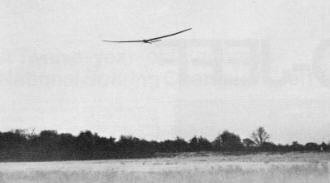
The
Astro-Jeff is elegant in the air, floating on the lightest lift, yet solid in
turbulence.
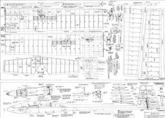
The Astro-Jeff
can be built with either a balsa or epoxy fuselage. The plans for either version
are available from AAM's Plan Service. (See page 86.) The
Astro-Jeff is available
in semi-kit form for $48.00, plus shipping (check your local UPS office for the
rate under 25 lb., and exceeding 84 inches combined length and girth), from Jeff's
Models, 6730 Halyard Road, Birmingham, Michigan 48010. The semi-kit includes: (A)
One assembled epoxy fiberglass fuselage; (B) One plastic canopy and dash; (C) Two
spring steel wing strut blades (WSB); (D) Two nylon wing strut channels (WSC) with
machined groove; (E) One fuselage strut box (FSB), machine grooved and assembled.
CONSTRUCTION
Fuselage: The epoxy fiberglass fuselage comes with both halves
assembled. Sand interior areas for epoxying, per instructions on plan. Use Hobbypoxy
No. 1 throughout, unless otherwise noted. Cut out the foam bulkhead, then epoxy
the antenna Nylaflow tubing in the bulkhead, and provide clearance for the rudder
push rod and a hole for the elevator Nyrod. Epoxy the bulkhead to fuselage. Fit
and epoxy the 1/4 x 1/4" spruce and 1/8" ply reinforcements. Cut out a slot for
the tow hook, and epoxy the maple tow hook mounting blocks. Add the 1/8" Sig Lite-Ply
support for the elevator Nyrod on the centerline of the fuselage. Trim the rear
of the fuselage (per section H-H) and fit FRP. Epoxy the ply reinforcements, as
shown in section A-A, making sure that the right side is longer than the left, and
leave space for FRP. Place the VFJ jig in place, and fit 4F. Epoxy 3F, 4F and FRP
in place. Drill out hinges for 1/32" hinge wire (RHP) and epoxy each in place.
After fabricating ECHP, drill a 1/8" hole for ECHP, making sure the hole is in
proper alignment (check by inserting a 1/8" tube and slighting from front). Install
ECHP and mark the location of the 2-56 screw. Drill and tap for same. Fabricate
ECH, and slot out the front hole in the vertical fin to match ECH.
Using the plan for templates, cut out two 1/8" ply root ribs. Clamp together
and drill location of the two screw eyes with a 1/16" drill. (These will be used
as dowel holes and to locate the remainder of the holes to the fuselage.) Drill
the other holes (1/8" and 3/16") and cut out the 1/16 x 5/8" slot for the steel
wing blade. Make this a close fit, so that proper alignment can be maintained. Mark
the ribs left/right and place on the fuselage. Line up the bottom front edge and
transfer the two 1/16" holes. Insert pieces of 1/16" wire (dowels) to hold and locate
the ribs to the fuselage. Drill the 1/8" and 3/16" holes. Drill 1/16" holes at the
top and bottom of the 1/16 x 5/8" slot. Remove the ribs, mark the opening for FSB
(use 1/16" holes for reference) and cut out. Do the other side and insert FSB through
the fuselage. (Note: The four center round-head screws can be removed and replaced.
After alignment, trim the width of FSB to fit the fuselage width.)
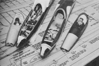
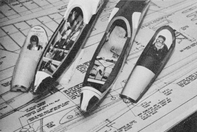
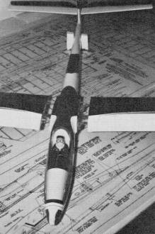
The radio compartment is spacious enough for any gear. The installation
on the left uses a different method of spoiler actuation than the one shown on the
plans, The spoiler linkage used in the
Astro-Jeff is very
simple to install and reliably accurate.
Place root ribs on the dowels in the fuselage and insert WSB through the ply
rib and into FSB. Support the fuselage by placing blocks under WSB (both sides),
and check alignment of the fuselage from the front to be sure that the fin is vertical.
Tack-glue FSB to the fuselage with epoxy. Do not epoxy the ply ribs to the fuselage.
When dry, remove blades, dowels and ribs.
Drill a 3/16" hole in the 1/2 x 3/4 x 5/8" pine block and locate it to the fuselage
(use 3/16" tubing to check squareness). Tack-glue in place with epoxy. When dry,
epoxy the pine block and FSB, using fiberglass cloth, as shown on plan. If eight-
or ten-oz. cloth is not available, use several layers of lighter cloth to obtain
the equivalent. Do not skimp on this reinforcement - use plenty of Hobbypoxy NO.2.
Remember to rough up surface of FSB to insure good adhesion of epoxy.
Cut out the slots for the wing rubber bands, add the spoiler Pro-rods, and canopy
hold-down block. Complete the radio installations at t is time. The Kraft installation
is shown and can be used as a guide. There is lots of room left, even for a thermal
sniffer.
Rudder: Cut out the ribs, using templates. Pin ribs to plan,
glue on the top spar, LE, top TE and cap strips. When all glue joints are set, remove
from plan and cut off the tabs from the ribs. Glue in the bottom spar, TE webbing
and spar webbing. Sand a bevel on the rear TE and glue in place. Next, glue in the
gussets and cap strips, Sand the end faces and add balsa blocks. Shape blocks per
plan. Locate hinge positions and epoxy in place. Drill the hinges and block, and
secure by epoxying in toothpicks. Epoxy the balsa fillers and control horn. Assemble
rudder, using RHP, and determine cap rib thickness between the fuselage and rudder.
Remove the rudder, add the cap strips and sand completely.
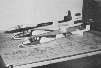
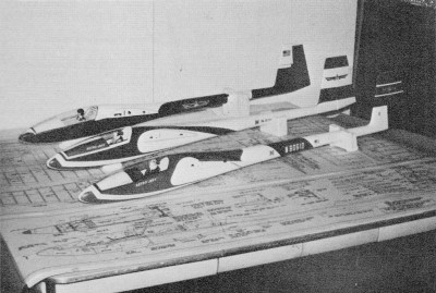
Three Astro-Jeff's on the author's workbench. Jeff's is in the
foreground, Jerry's is next, and the balsa version is in the back.
Elevator: Cut out the two aluminum templates 4E and 10E.Stack
14 pieces of balsa, clamp together with screws, and shape ribs. Use the plan templates
to cut out ply ribs 1, 2, and 3 (make two of each). Stack pairs of" ribs and drill
1/8" holes for the brass tubes, making sure that this dimension is the same as ECH.
Make sure that there are tabs on all ribs for building purposes. Pin the spruce
spar to the plan and glue all ribs. (Don't forget to tilt the root rib for dihedral.)
Glue TE, LE, top spar and cap strips. When dry, remove from plan and remove tabs
from the ribs. Glue the TE and TE webbing, after sanding bevel on the 1/16 x 3/16"
TE and cap strips. Plug the tube ends and epoxy in place. Glue on balsa ribs and
balsa tip blocks. Contour the" balsa rib to the vertical fin and sand completely.
Center Wing Section: Make aluminum templates for all balsa wing
ribs (seven templates required). Cut balsa for stacking, with appropriate template
ribs 1BF through 11BF, 1BR through 11BR, 12B through 22B, and 23B through 37B. (Note:
22B and 23B are identical templates, except for spar width, so cut accordingly.)
Assemble stacks, drill holes and bolt together with long screws, or fabricate screws
using bicycle spokes. Both right and left ribs can be cut together. If both right
and left ribs are cut together, mark alternate ribs Rand L when disassembling stack
to maintain a consistent taper. Add 3/16" holes to ribs 1BF through 8BF for spoiler
Pro-rod (5/16" from bottom of rib, other dimensions on plan).
The tail feathers of this bird are well-proportioned. That large
rudder makes for solid response.
Fabricate the spar box as follows:
Glue VWR to top and bottom spars. (Glue VWM and five pieces of 1/8 x 3/8" Sig
Lite-Ply braces, fitted to length. Determine thickness of RN by stacking FN and
WSC. The total thickness of these, when subtracted from the 3/8" spar, is the thickness
of RN (nylon sheet has a .03 tolerance, and this variation is made up with RN).
Rough up the top, bottom and rear of WSC (nylon) for better adhesion. Epoxy RN
to VWR (between spars), and WSC to RN (Hobbypoxy 1 or 2). Coat WSB (steel blade)
with light oil, or silicone film, and place in WSC (oil film will prevent epoxying
WSB in place). Epoxy FN to WSC and spars. Glue or epoxy VWF to FN and spars. Place
this assembly in position on sheeting, with root rib in place to insure proper alignment,
and clamp the entire assembly (do not glue root rib to sheeting). Slide WSB to insure
slip fit. Make sure VWR/VWF match spars, and check ribs 1 BF through 11 BF for correct
height with spar box. Let the above assembly dry thoroughly, then wrap with nylon
thread, per plan.
Pin down and glue bottom sheeting, cap strips and stringers. Sand spar box assembly
square at the root rib and glue to bottom sheeting. Glue on the false leading edge.
Notch the ribs to accept the stringers and glue ribs 1 through 11, front and rear,
along with 12B. Cut a strip from 1/8" hard balsa 181/4" long for horizontal webbing
(check height between spars on ribs 12 and 21 for dimensions). Cut these pieces
with excess length, and glue webbing and ribs 12 to 21B in place. Glue in PB1, PB2,
and PB3. Cut 22B to fit and tilt, per plan. Add re webbing (grain is horizontal),
gussets and top stringers. Slide WSB into the spar box and glue in the root rib.
Add spoiler linkage and Pro-rod. The inner portion of the Pro-rod should be cut
off to a known dimension, at the root rib, for reference. Use the plan as a guide.
When making SW (spoiler wire), be sure that there is enough clearance in the Ace
Swing-in-Keeper to provide a swiveling effect with the keeper. If using 1/16 wire,
drill keeper with a No. 50 (.070) drill. Glue in the screw eye and. tubing reinforcements,
and epoxy the 5/32" OD brass tubing.
 Sand a bevel on the underside of the top
rear TE and glue. Frame the spoiler opening with balsa, per plan. Shape the top
of the front false LE, and glue all top sheeting and cap strips. Sand a bevel on the underside of the top
rear TE and glue. Frame the spoiler opening with balsa, per plan. Shape the top
of the front false LE, and glue all top sheeting and cap strips.
Spoiler Construction: Cut ply to fit opening, with 1/32" clearance
on back and two sides. Layout holes per plan, stack ply top to top, clamp to board
and drill holes. Use Hobbypoxy 1 for gluing spars, while they are clamped to a rigid
surface. I recommend a combination square ruler. Epoxy in place ribs S1, S2, linkage
lever rib and spring return rib. Clamp ribs with clothes pins.
The spoiler has the curvature of the wing, so place the spoiler ribs (per plan)
for right and left, to avoid interference with balsa ribs. Insert 1/8" ID brass
eyelet and crimp over in the linkage lever, as shown in enlarged view S. Fit spoiler
in wing opening, and notch balsa ribs to miss spoiler spars.
Outer Wing Section: Pin bottom sheeting and TE to plan. Glue
cap strips and bottom spar in place. Mark completed inner wing panel for the 36"
polyhedral point, as shown on plan. Block up 3-1/4" at this point, and glue PB1,
PB2 and PB3 to spar and bottoming sheeting, making sure to bend PB1 as shown. Glue
in false LE and ribs. Place washout shim at TE, glue in top spar, and three thicknesses
of vertical webbing. Also glue in the TE horizontal webbing and gussets. Sand the
top of the false LE, and glue on the top sheeting, TE (bevel underside of TE) and
cap strips. Sand LE and glue on the hard balsa LE. Sand the wing tip and glue on
the tip blocks. Shape the LE and sand the complete wing. Use MonoKote or equivalent
for spoiler hinge.
Make SS (spoiler swivel) and file a screw, so that the screw clamps SW, but has
clearance for the brass eyelet. Add spring and adjust.
A double wing securing system is necessary, so that the spoiler
linkage will remain in" equilibrium. Any amount of gap between the wing and fuse
would delay spoiler actuation, thus causing an aileron effect in flight.
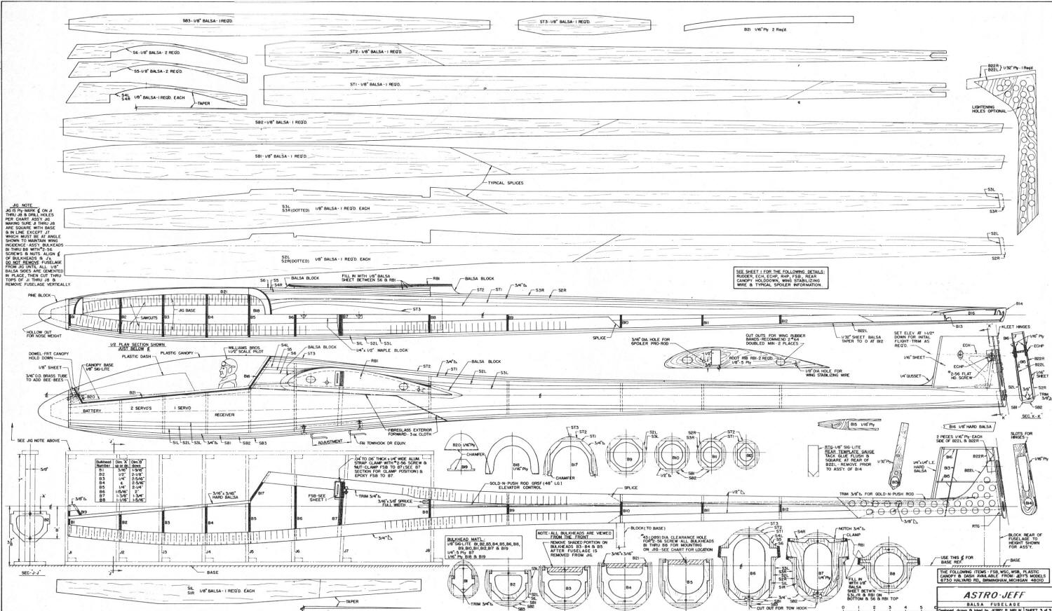
Balsa Fuselage Construction: Begin by cutting out all bulkheads
B1 through B12, using templates as shown on plans. Using 1/8" Sig Lite-Ply, except
B7, which is 1/4" ply. Bulkheads B3, B4 and B5 include shaded portion for initial
build-up on the jig. Mark a vertical centerline on the bulkheads, and drill out
the two holes for attaching to its corresponding jig piece (see charts for dimensions).
Make jig from any grade commercial plywood, making sure that the vertical members
J1 through J8 are 5/8" wide. Mark the vertical and horizontal centerlines in the
J pieces, and layout the top hole (see chart for dimensions).
Drill a clearance hole, and assemble the bulkhead with bolt and nut, lining up
the two matching vertical centerlines. Tighten the bolt, clamp bulkhead to jig piece
and drill bottom clearance hole (using bulkhead as a jig). Repeat procedure for
all eight bulkheads and jig pieces. Disassemble bulkheads. Mark jig base with fuselage
centerline. Glue and nail jig together, making sure that the jig is square and that
the centerlines are aligned. Use plan for spacing J1 through J8, making sure that
the angle of J7 is maintained. This bulkhead sets up the incidence in the wing.
Let the jig dry.
Cut the 3/4" triangular longerons with a razor saw in two directions (perpendicular
to its length, as shown on plan) so that it will bend to the contour. Make right
and left longerons. Splice and glue the 3/8", 1/2" and 3/4" triangular longerons,
leaving the front long (trim it later). Leave the right rear bottom longer for the
angle at the rear. Cut out B22-L, B22-R, B13 and RTG (gauge). Glue B22-L and B22-R
to its 3/8" triangular stock (the bottom is flush). Trim the 3/8" and 1/2" triangular
stock to accept B12, B13 and RTG. Glue B10, B11 and B12 to the plan view, and tack-glue
RTG. Cut out B15 and glue B13 (with B15) .to B22-R and B22-L.
Place jig on plan view, lining up centerline. Anchor it to the building board.
Assemble bulkheads B1 through B8 to jig, with screws and nuts. Glue in the 3/16
x 3/16" front stringers. Cut out and glue B19 in place, and glue 3/8" triangular
stock at the front. Make aluminum clamps and epoxy F5B to B7. Clamp should be inside
the outer edge of B7 by at least 1/8", leaving room for RB 1. Check alignment by
inserting W5B.
Place jig blocks at the rear of the fuselage and at B 10 (see side view for dimensions).
Glue the bottom assembled longerons to B7 and B8 (hold in place with rubber bands)
and place on the two jig blocks. Glue the top, right and left longerons (trim like
the bottom ones) to B13, B12, B11 and B10 (clamp around with rubber bands). Glue
B9 and clamp. So far, the triangular stock should be flush with the bulkheads on
all sides. Continue gluing and clamping the triangular stock to the bulkheads, while
fitting it at B1. Trim the inside edge, per section B1. Cut out and glue B17. Glue
3/16 x 3/8" spruce to B8. Glue 1/32" sheet filler in front of B22-R/B22-L, and sand
to plan taper when dry. Do not remove from jig.
Cut out, add taper and glue 51-L/51-R (the taper goes outside) to B1 through
B8 and the 3/4" longerons. Cut out, add taper and glue 54-L/54-R to B17, B6, B7,
B8 and the top 3/4" longerons.
Add the elevator Nyrod, fitting it at the rear and through B13. This is a good
time to think about the antenna too. You can epoxy a 3/16" 00 Nylaflow tubing the
full antenna length, while putting the actual antenna inside a 1/8 00 Nylaflow tubing.
Tie a knot in the antenna wire end and slip this through the other tubing.
Cut out 52-L/52-R, the two pieces of 55, 53-L/53-R and the two pieces of 56 per
template shown and glue to jigged fuselage in the sequence noted above, Cut out
RBIs along with the wing root ribs, as shown on plan sheet two. Drill corresponding
holes, while stacking these four pieces to insure proper alignment. Cut out, drill
hole and epoxy the 1/2 x 3/4 x 5/8" pine block used for the spoiler, as shown on
plan sheet one, Fill in the space between 56 and RBI with 1/8" balsa sheet, fit
and glue.
5and the rear of the fuselage. Remove RTG, cut out B14 and glue. Glue the four
pieces of 1/16" ply to B22-L/B22-R and B14. Drill a 1/8" hole for ECHP (see section
K-K). Fabricate ECHP and assemble. Mark hole location and drill and tap for 2-56
screw. Cut out and glue B16 and LE of fin.
Saw the upper end of J 1 to J8 and remove the top of the jig. Remove all screws
holding the bulkheads to the jig. Remove fuselage by lifting vertically.
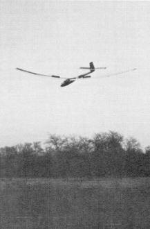
Spoilers deployed, the
Astro-Jeff becomes
a real target drone, capable of zeroing in on the landing spot.
Cut a piece of 1/4 x 1/2" to the required length for anchoring your tow hook.
Add blind nuts and glue block to B6/B7.
Cut out 5B1, 5T1, 5B2, 5T2, 5B3, and 5T3 per plan template, and glue to fuselage
in sequence noted above. Glue in the 1/4" gusset and 1/16" sheet on vertical fin.
Add extra 1/16" sheet at the base of the fin for a fillet (see section H-H).
Fill in space between 53-L/R and RBI with 1/8" balsa sheet, fit and glue. Glue
balsa blocks in the space at the front and rear of RBI and the fuselage. Glue 1/8"
balsa on the top side of nose. 5and the canopy opening and glue B21, B20 and B18.
Drill hole in B1/B20 and epoxy tubing in place. Hollow out the pine nose block (can
be made in two pieces and glued) and shape to outline of B1 section prior to gluing.
Get a big basket and start shaving. I used a small X-acto razor plane and very
course sandpaper block, while keeping an eye on the various sections B 1 through
B12. You can see the different sheets and triangular stock change with the eye.
It is really fun now. For the fillets, use sandpaper on a dowel. The larger the
dowel, the larger the fillet.
Cut out the tow hook opening and fiberglass with Hobbypoxy 1 or 2 and three-oz.
cloth. Remove shaded area from B3, B4 and B5 by sawing. Make canopy, radio installation,
and push rods and you're ready to apply the finish. I'll leave the rest to your
preference.
Finish: The finishing method used was MonoKote on all flying
surfaces, and the fiberglass fuselage was painted with Ditzler Acrylic Lacquer.
Before you go to the the flying field, check all surfaces for warps, and assemble
the e rudder, stabs and wing. Check all controls for proper function and make sure
that the linkages are not sloppy. Add nose weight until the model balances at the
CG shown. Make sure that you 1-1/2° down elevator when the transmitter is at neutral
and the trim is centered. Place the tow hook approximately 3/4" forward of the CG.
Disassemble the model, pack up and head f or the field. Before flying, range
check the equipment again. You have made a new installation, so don't rush it-make
sure to try your controls again! Oh yes, do you have the frequency pin? If there
is a slight breeze, don't use a hi-start for the first flight, since you have not
optimized the tow hook position. If you have a strong arm, give it a strong throw
and check it out. When you're satisfied, hook it up to the winch line, point the
nose up about 300, tighten the line and keep standing on the winch to obtain sufficient
height before pulsing the winch and release. Get the model to fly level hands-off
and see what it's doing by checking right and left turns. Smooth out the turns and
you're on your way. Make long approaches on the initial landings, until you get
the feel of it. Make several flights, moving the tow hook back to a comfortable
towing position. The Astro-Jeff
will really tow up, so work at it. I would recommend that when you're ready to try
the spoilers, you don't start at low altitude. Instead, start up 25 to 30 feet,
then put the spoilers up slowly and be ready to apply up elevator. Play with coordinating
the spoiler with up elevator, and the spots will comes with practice. If you have
any questions or comments, contact me through AAM.
<click for larger version>
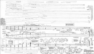
<click for larger version>
All rights to the Astro-Jeff
are now owned by Mr. Jim Ealy. He has done the soaring world a great service by
making this exceptional craft - available in kit and short-kit form at the
Vintage Sailplaner
website.
Notice:
The AMA Plans Service offers a
full-size version of many of the plans show here at a very reasonable cost. They
will scale the plans any size for you. It is always best to buy printed plans because
my scanner versions often have distortions that can cause parts to fit poorly. Purchasing
plans also help to support the operation of the
Academy of Model Aeronautics - the #1
advocate for model aviation throughout the world. If the AMA no longer has this
plan on file, I will be glad to send you my higher resolution version.
Try my Scale Calculator for
Model Airplane Plans.
Posted September 1, 2022
(originally published on 7/24/2010)
|