|
The Academy of Model Aeronautics
is granted tax-exempt status because part of its charter is for activity as an educational
organization. I think as time goes on, it gets harder for the AMA for fulfill that
part of its mission because presenting anything even vaguely resembling mathematics
or science to kids (or to most adults for that matter), is the kiss of death for
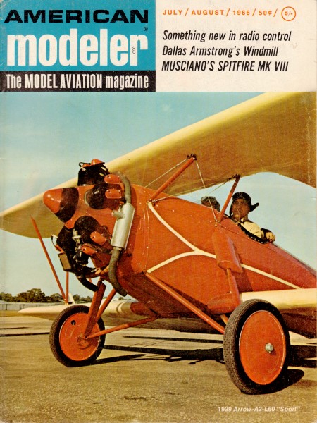
gaining or retaining interest. This article, "Control-Line Aerodynamics Made Painless,"
was printed in the July/August 1966 edition of American Modeler, when graphs,
charts, and equations were not eschewed by modelers. It is awesome. On rare occasions
a similar type article will appear nowadays in Model Aviation for topics
like basic aerodynamics and battery / motor parameters. Nowadays, it seems, the
most rigorous classroom material that the AMA can manage to slip into schools is
a box of gliders and a PowerPoint presentation. That and a few scholarships each
year keep the tax status safe... for now.
This is part one of a series of technical articles on the aerodynamics of control-line
flying. It appeared in the July/August 1966 edition of American modeler. Here is
Part 3.
Control-Line Aerodynamics Made Painless
By Bill Netzeband
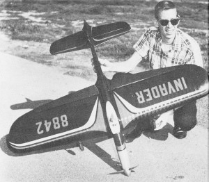
Roger Wildman with his Invader, one of several aerobatic aircraft
used to check out calculations. Weighs 60 ozs., McCoy 0.40, 600 squares, 48 mph.
Crewcut Bill goes long-hair! And he has conspirators, many of the nation's leading
designers. Line rake angle is an all-important factor, they agree.
Since the beginning of control-line models, back in the 40's, the design phase,
viewed from published information, has been a "black art" relying on phases of the
moon, superstition, etc. "Designers" appeared to ignore, or misunderstand, the unique
effects of flying in circles tied to a pilot in the center.
WWe were told to balance the model on front lead-out; or balance it on the bellcrank
pivot; or to balance one thumbprint forward of the main spar, or any other such
nonsense that popped into a designer's head. All we really knew was that his model
balanced there and he liked it! Always they were half right-and half wrong. Actually,
we lived by the "Flea Fright" practice of adjusting each ship to tailor out the
kinks, if it survived the first flight! Ultimately, we were subjected to a lot of
marginal designs (mine, too) flown by talented pilots who took it upon themselves
to explain phenomena they didn't understand. Luckily, we do not wipe out pilots
during crashes.
Back in 1951 I started serious investigation into miniature aerodynamics. It
is simply a matter of applying classic aerodynamics to our size whenever we could.
The principles, happily enough, apply directly; the problems are in the constants.
Guess and test methods were used to backup mathematical correction of lift, drag
and inertia factors, finally coming up with "numbers" useful to our size airplanes.
One slight point irks me. Only a scale model of a man-carrying airplane qualifies
for the name "model." If we design an airplane for a specific performance criterion,
then it's an airplane, no matter how small!
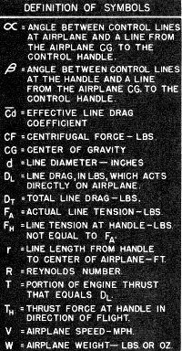
Definition of equation symbols.
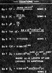
Control line physics equations.
In future issue we'll present a generous portion of concentrated CL aerodynamics;
concentrated meaning, any mathematical procedure will be explained in English and
useful equations will be reduced to simple nomographs. We will be shooting for those
of you interested in knowing Why and How, but who have not elected to follow a career
in engineering or science. We assume that Math and Aero majors will be reading very
critically looking for mistakes!
Basic Physical Facts: This installment covers a phenomenon not
recognized in any other branch of science, at least not in books I've been able
to read. So we had to develop our solution. We tie our airplane to a handle, pick
up that handle and stand there while the airplane zooms around us. The physical
reactions caused by moving a body (object) in a hemispherical plane, supported by
thin flexible lines, with motive power applied at the object, are unique to CL airplanes.
Flying above the handle introduces forces not covered in classic aerodynamic
work, and the effects of the lines themselves are interesting. Our phenomenon is
the curve that appears in the lines: How do we measure it accurately, its effect
on the airplane, and what do we do in the design of the airplane to achieve the
best performance? Where should the line-guide be located?
Since Isaac Newton discovered that an object pulled by a force tends to move
in a straight line, we must apply another force to make that object move in a circle.
This is called Centripetal Force, which you apply at the handle. There then exists
an equal and opposite force to balance it called Centrifugal Force. (EQ 1) These
two keep the circle round because, if unbalanced, like a broken line, the object
heads back toward its straight line. The amount of centripetal force is determined
by the weight of the airplane, the angular rate at which it moves around the circle,
and the length of the lines. For our purposes we convert angular velocity to tangential
velocity and call this the airplane speed (V) generally in miles per hour (mph).
By convention, we make lines to a length which will give standard distance from
handle to airplane centerline. The center of gravity (CG) of the airplane is very
close to center-line, so we now state that airplane speed (V) is that of CG. To
simplify matters let's assume the Thrust of the prop passes through the CG. This
done we could throwaway the airplane and use a dimensionless lump, same weight,
at the CG. If it were possible to mount the bellcrank pivot exactly on the CG and
the load of each line didn't change (it does) we could fly without a line guide.
Since precise location is not practical, we add some form of line support between
the bellcrank and the handle. After adding the line-guide one problem is solved,
another created. For years we were fooled into believing that the position of the
bellcrank in the airplane controlled its attitude. Not so. The bellcrank can be
almost anywhere in the airplane.
A simple cardboard outline of an airplane will show this relation (photograph
in continued portion). Place an eye (U-shaped bent pin) in one wing tip and tie
a pin on the end of a thread. Run the thread through the eye and stick a pin anywhere
in the cardboard.
Observe how the thing hangs and then move the pin (string end) to some other
location. Right! Anywhere you stick that pin the airplane hangs the same. Now move
the eye (line-guide). The airplane assumes some new position. The CG of the airplane
will line up with the line-guide. (Note: It would be nice to mount the bell crank
on a line between the CG and the line-guide, because the control lines could lead
straight through the line-guide, therefore operating with the least stiffness.)
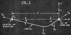
Figure I - Crux of the matter. Behind the charts stands years
of flight testing.
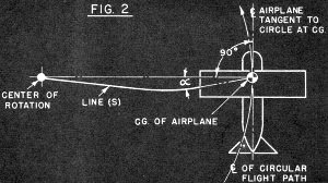
Figure 2 - Control line cable sag due to wind force.
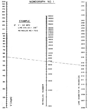
Nomograph 1 - Airspeed, Reynolds number, line diameter.
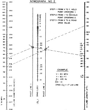
Nomograph 2 - Airspeed, line drag, line length.
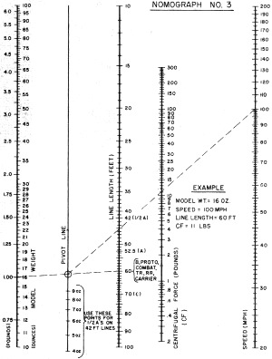
Nomograph 3 - Weight, line length, centrifugal force, airspeed.
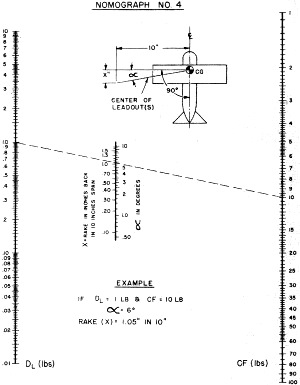
Nomograph 4 - Control line drag, line angle, force.
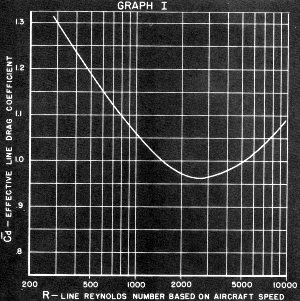
Graph I -Reynolds number vs. effective drag.
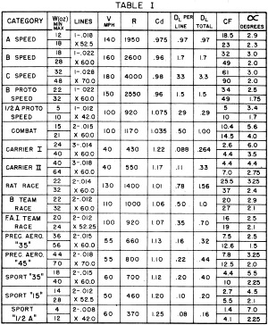
Table I - Summarization of airplane, engine, line length and
weight, wind resistance, etc.
We must qualify the above facts by stating that the line must be very flexible
compared to the weight of the airplane. A perfectly flexible wire can carry no side
load without bending. Misplaced bell crank side load is re-acted inside the airplane,
not appear as an aerodynamic force. Notice that this effect is factual for the fore-and-aft
and also the vertical position of the CG. Were you to use say 1/16-in. diameter
lead-outs on a V2 A ship, running them beyond the line guide 4% or 5% of the total
line length, and then placing the bell crank at a kooky position, you have established
an exception. All practical cases so far.
The next problem is line shape. Closest parallel in engineering mechanics is
the Catenary, a curved line between two points similar to a slack flexible cord
hanging between two poles. This cord is assumed to be carrying only its own weight
(uniformly distributed load) and its hangs in a mathematically predictable shape.
The point of maximum deflection from a straight line between the support points
is in the exact center of the wire. The deflection is inversely proportional to
the tension in the line (more tension, smaller deflection), and directly proportional
to the weight of the lines. You can demonstrate this one with a piece of control
line, so we'll not describe the experiment. It will prove that in horizontal flight
your lines will droop from gravity causing a slight vertical angle leading into
the airplane CG. For most airplanes "going around flat and fast" this angle is too
small to measure.
To determine line shape in the horizontal plane (top view), we resort to forces
shown in Fig. 1. Here the load on the line is not uniformly distributed. Load is
caused by aerodynamic drag which is proportional to a constant times velocity squared.
The velocity of the wire is assumed to be zero at the handle end (as in a pylon)
and increases directly proportional to the distance away from the handle finally
reaching airplane speed (V). Therefore, each little piece of line travels at a different
velocity. This dictates the process of mathematical summation to find line drag.
(More later.) To move this force system we apply thrust (T) to the CG, T being just
enough to carry the effective line drag (DL). To establish equilibrium in the system
we need a thrust at the handle (TH). Surprised? Fact is, without a pylon, whipping
is a way of life. (Say it isn't so!-Ed.) At a later time we'll show how to whip
best. But back to the lines.
It is conventional in vector analysis to resolve a vector (a force with a definite
magnitude and direction) into two vectors 90° apart, or vice versa. Thus, vector
force FA (line tension) is the combined result of T and CF. It has an angular relationship
to both, but we're interested in its angular relation to the line of action for
CF. This is (∞) Eq. 2. Likewise angle (f3) Eq. 3 is related to FH, TH and Centripetal
Force (not shown). Once we know (∞) we know where to place the line guide! The development
of an exact equation for (∞) was a laborious chore. We'll not cover every detail,
but a brief history should be enlightening.
Math Solution Development: Progress started in response to my
published force diagram inside the airplane during the March/April 1963 CLC column
in this magazine. Basically, it referred a portion of the line drag (DL) equal to
(T) applied to the line-guide. This may not be 100% valid, since the lines slide
through holes, but wear on the back of such holes proves some force exists. Right
or wrong, we then searched out a coupling force to keep the airplane from turning
into the circle. The reacting couple turned out to be CF and Centripetal force if
the CG were moved forward in space to develop an arm between them. The resultant
angle turned out to be exactly the amount as (∞) from the last paragraph.
When the bellcrank center is exactly on the CG, and if thrust is exactly through
the CG the force at the line guide will disappear, if (∞) is correct. It should
be reemphasized that bell crank pivot should be close to the CG, to reduce the bending
at the line-guide which can cause stiff controls. At the time we didn't have a reliable
drag coefficient for the lines, so progress ceased.
Receipt of math from Rex Powell and Charles Klabunde provided an equation for
line shape and angles (∞) and (β) Eq. 4. They had some trouble agreeing on drag
coefficient (Cd), otherwise complete agreement existed. Their work disclosed that
with proper manipulation and substitution (∞) was indeed proportional to the ratio
of DL to CF. Also they proved the centroid of line drag was at a point three-quarters
of the distance out from the handle. Thus airplane thrust is three times handle
thrust. It was further shown that since both DL and CF are proportional to V2, the
system angles should be independent of velocity. This turns up frequently in our
aerodynamics and, when estimating, we take advantage of it. However, Mom Nature
wasn't so kind as all that there. (Figures-Ed.) Enter the villain in this piece,
Mr. Reynold's marvelous number.
Osborne Reynolds was first to discover, understand and define the effects of
object size, shape, speed of flow and viscosity of medium. Crudely put, he found
that if two objects have the same shape but different size they will not have the
same drag coefficient (or lift coefficient), unless speeds of flow and viscosity
are varied to make their Reynolds numbers equal. (Eq. 5) is a simplified version
of this with the viscosity held constant for air under NACA standard conditions
of pressure and temperature.
When this is done, R becomes proportional to V and "some dimension defining length
in the direction of flow." This dimension in our case is (d) the dia. of our lines
in inches. Our lines are the same diameter from handle to airplane, the same shape,
and air viscosity is constant, but (V) varies. So we can't completely ignore velocity
because Cd does not remain constant from handle to airplane.
Reverting to experimental data, by old timers, it was found that, over our range
of interest in R, Cd wandered from 2.4 or higher to around 0.98. Three different
people ran experiments that appeared to agree well enough to believe. Unfortunately,
the variation wouldn't nicely convert to an equation so we could plug it in. We
were held for the moment to saying "Let's use CD = I." This gave a fairly reasonable
number considering we were looking at thin, dirty, vibrating lines. But there was
more to come.
Ed Fort sent along a complete line-drag equation using an approximate equation
for Cd as estimated by F. Eisner (Eq. 6). By substituting for R in terms of V and
d, and solving a definite integral he allowed as how total line drag was per Eq.
7. One glitch in this Cd, it continued decreasing where experimental data proved
an increase occurred. This would cause error in large lines and high-speed airplanes
like C-Speed ships. But it was the best yet.
We made a nomograph of this one, congratulating ourselves and all concerned.
Meanwhile Pete Soule confirmed Rex's and Charles' work tying in nicely with my stuff
and picking Cd = 1. (We were going to publish the results but job changes, fires
etc. short-stopped that.) We tried it out on several models with reasonable experimental
results. (It was close!)
Pete Soule showed up one evening with a solution giving "effective line drag"
based on thrust horsepower used to pull a portion of the lines (Eq, 8). He had also
resolved the Cd problem by finding an "effective drag coefficient" based upon the
Reynolds number of a line traveling at airplane speed. This bit involved complex
curve fitting by Gaussian Quadrature (Who he?-Ed.), and I'll leave it lying right
there. The validity is unquestionable so we constructed the final nomographs which
appear here. You think that part was tough? Those are the answers. You should have
been around for the questions!
Two other gentlemen got in hot licks. Piper Mason went at the problem with a
jet model and careful observations, outlining a good test method. Bob Ormiston's
observations pretty well concurred with what we finally got. What did we get, you
ask?
We Got Results:
1. An angle between the CG and the line-guide which if built into an airplane
will fly that airplane squarely tangent to the circle; theoretically providing least
drag, most thrust and good line tension.
2. If you don't want to fly squarely tangent to the circle, you can correctly
bias the angle to suit your whim. No Guesswork when yawing in or out.
3. An exact method of determining the line drag the engine has to move. This
will lead down the musty corridors to finding airplane drag coefficients, measuring
the effect of streamlining, engine hop-up, prop thrust etc. We still need 1% accurate
engine Bhp characteristics and any kind of propeller thrust data.
4. A basis for evaluating the best techniques for "whipping."
And we finally opened a door that was closed.
Practical Considerations:
For about two years we subjected the calculated results to flight testing. Speed
work by Roger Theobald, TR by Pete Soule, Rat and TR by John Barr. Stunt by Roger
Wildman and "li'l ole line-maker me" dashing around with Combat, Carrier and 1/2-bugging
all concerned. Each time we carefully adjusted speed and CG-to-line-guide relation
to airplane weight we confirmed the accuracy of the calculations.
Just to keep it from being too simple we got "wind." Real briefly; wind, when
headed directly into, causes an additional line-drag load, this one uniform (like
the catenary) so TH and T to balance it are equal. It can be troublesome since V
is not increased and is sometimes decreased which means ∞ will get larger. Upwind
the nose pulls in. Downwind the effect is opposite. Jolly old experience (the results
of poor judgment) shows us the ½A through 0.15 sport airplanes and all stunt types
need increased line rake for breezy flying. Reasoning process, backed by flight
work, says for large Cd, like with slow velocities and small lines, the build up
of drag is more drastic. Also, slow basic speeds (around 50 mph) mean a 30-mph wind
is over 50% of the base speed. So we simply provide these air-planes with extra
holes in the line guide to increase rake in 1½° intervals.
If your ½A is stuck with one leadout location add 15 mph when calculating DL.
This about covers a 30-mph wind condition. A stunt ship should be flown with rake
as close to ideal as possible to hold down lateral glitching on tight(?) corners.
Half-A's generally are marginal on basic line tension, so we must guarantee that
they'll stay under control. Speed jobs are still subject to more testing, but don't
bother correcting for wind. Combat, Rat and TR ships have worked out best with ideal
calculated angles. Carrier ships are calculated at 40 mph speed to cover the speed
range accurately.
Look over Table 1 for some extreme values in any category. Lines used are either
required by rules or "most used" size. Weights are a little "outside" both directions.
Final numbers pretty well box in each category. Numbers are "straight", no adjustment
for wind.
How about engine offset and rudder? The facts vary widely so that each case is
a new game. The CF-DL force is much larger than the combined forces of any normal
engine offset or normal rudder area. Again Stunt and ½A sport must be evaluated
each to its own. IF you build-in the right ∞, bad judgment on engine offset and
rudder area won't hurt much. Incidentally, the side force from engine offset isn't
what we look for, unless you put in 100 or more. We examine the thrust line's distance
in-board of the CG (it had better be inboard) to evaluate its turning moment to
keep the nose headed properly under all weird conditions.
If you want to tell me about that extreme case that shoots all this down, be
very certain you send all of the facts! There are no mysteries; only a lack of complete
knowledge.
We have not deliberately ignored the Scale buffs. Your problems are always very
special and we recommend that you play the game straight. It was convenient to end
the weight scale on Nomograph 4 at 100 ounces, but if you have something heavier,
divide the weight by 2, perform the calculation and double the CF. Nomographs and
Procedures: The nomograph is a handy tool, similar in operation to a slide rule,
in that logarithms of numbers are added or subtracted geometrically to perform multiplication
or division. The two dimensional layout essentially operates on the principle of
similar triangles allowing answer or pivot line's location to automatically include
constant factors. Each nomograph is designed to solve a specific equation; making
it ideal for often-used calculations. The only other tools necessary are a straight
edge, preferably clear plastic (and very straight) and a thin sharp pointed instrument
(like a pencil). Throughout the projected series we will provide nomographs for
all significant mathematics.
Finally, the nomograph generally allows slide rule accuracy, always precise enough
to match our building capabilities. Our nomographs will be designed to start on
outside scales (Left and Right), working through pivot lines 1 and/or 2 and the
inside scales toward the answer. After you gain experience you'll find that they
can be solved in different order to work backwards toward some independent variable.
[Example-Find weight of airplane on 60'x.015 dia. lines to generate 50# of CF @
100 mph. (Ans. 4½ lb.)]
For practice you might solve the examples in Table I to see how estimates of
points are handled. Let's take the "Sport 35" at 18 ounces for a trial run. Step
by step: (Note-Examples shown on Nomographs are to demonstrate procedure only).
A. Reynolds Number from Nomograph
I
1. Place pointer on V scale (LH) at 60 mph.
2. Slide straight edge firmly against pointer and move right end until it lines
up with 0.015 line diameter on RH scale.
3. Read answer of 700 from center scale.
Now you have the whole basis. Hit the first point with pointer, slide straight
edge to it, swing edge to other point and read.
B. (Cd). This one is simply read from Graph I.
Note that the R scale is logarithmic, the Cd scale is linear and use your noodle
when estimating. Cd in our case is 1.12. C.
Drag for One Line-Nomograph 2
1. Pointer on 60 mph (LH outside) (V)
2. Straight edge from pointer to 60' line length (r) (RH outside)
3. This time instead of reading, lift pointer and move over to where the straight
edge crosses Pivot Line 1. Place pointer there.
4. Holding edge against point on PL 1 swing edge down to 1.12 on the Cd scale
(inside R H).
5. Pick up and hold point at Pivot Line 2.
6. Holding point at PL 2, swing left edge down to 0.015 line dia. (d).
7. Now read the answer from Drag scale (DL) (0.20 lb/line ).
D. Centrifugal Force-Nomograph
3
1. Pick up model weight (18 oz.) on LH scale using inside divisions.
2. Set straight edge to cross line length scale at 60'.
3. Pick up and hold crossing of Pivot Line.
4. Swing edge up to 60 mph on RH Speed scale.
5. Read answer from CF scale as 4.4 lbs.
E. Rake angle-Nomograph
4
1. Determine line drag (DL) by multiplying DL from step (C) by the number of
lines. (2 x 0.20 = 0.40#)
2. Pick up line drag on DL (LH scale) at 0.40 lb.
3. Set up straight edge to cross CF (RH scale) at 4.4 lbs.
4. Finally! Rear rake either in degrees (5.5°) or in inches back in 10" of span
(0.98" in 10"). The latter method is a bit more accurate for layout purposes, particularly
if you don't have a good big protractor.
The whole operation should take less than 5 minutes and both speed and ac-curacy
improve with practice.
Wrap Up:
One last item. The angle we calculate is partially phantom, in that it falls
exactly half way between the line guide holes for a two-line system, when the lines
are equally loaded. That "equally loaded" is important. As the elevator is moved
from neutral the point shifts to the line under greater tension. If you operate
a limited bell crank movement, as in combat, the load will be carried completely
by either wire during maneuvers and the point of action will coincide with that
lead out. These facts dictate that line-guide holes should be very close together
or through the same hole. One' hole is practical only if you connect the clips inside
the wing, or if you stagger the leadout ends. Otherwise the holes should never be
farther apart than one inch, preferably closer than a half inch.
With a three-line Robert's system it is conventional that pull on the middle
line closes the throttle. It is desirable to bring this line out closer to the aft
line, also arranging controls so that the aft line is "UP". This trick will allow
slow flight at maximum yaw angle. The over-and-under lead-out system in Stunt is
somewhat shaky, since the airplane responds in the lateral direction (roll), generally
unfavorably, if you're looking for maximum smoothness in sharp comers.
If, perchance, your use of these data shows apparent errors, please try to consider
every variable involved before you condemn us. Many carefully observed experiments
have been performed to establish our high degree of confidence. If you still have
trouble ship us every bit of information and we'll check it out.
Posted June 8, 2021
(updated from original post on 2/6/2011)
|