|
Here
is a nice, quick project if you have ever wanted to try your hand
at an amphibious model airplane. The Shoehorn was originally designed
and built as an .049-powered free flight job with a 32" wingspan,
but with today's miniature radio systems it could easily be converted
to 3-channel operation. For that matter, you can substitute a brushless
electric motor for the glow fuel engine that, along with today's
high density, low weight Li-Po batteries, would easily provide as
much power as the .049. The Shoehorn is of built-up balsa construction
with Silkspan and dope covering, but of course there you could substitute
iron-on plastic covering available for park flyers (which this would
have been considered if park flyers had a name back then).
See all
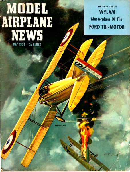
Model Airplanes News items. Shoehorn Amphibious Model
Airplane
by H. A. Williamson
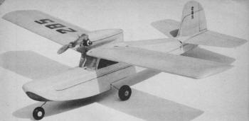
More apparent features include the lowest possible thrust
line for this type design, and trike gear - all wheels "retract"
for water operation. |
This is the time of year when fancy turns to hydro flying. And with
a classy boat like this Half-A to try, season gets started with
a splash. It's amphibious. Evidence of the growing popularity
of hydro flying was established this year with the inception of
several all ROW contests, that included Payload, radio control and
flying scale events, all run on the briny deep. Speedy runabouts
replaced the old familiar "chase cars." One of the contributing
factors in the sudden interest in ROW models is, undoubtedly, the
almost depleted source of suitable land flying sites, particularly
along the East Coast. Another factor, perhaps, may be the desire
on the part of many modelers to get away from the "Cut and dried"
classes and try some new and relatively unexplored fields. Admittedly,
there has always been a fair amount of interest in the free flight
ROW events, particularly at the Nationals. Unfortunately, these
models have seldom, if ever, in recent years, reflected any especially
noteworthy hydro design. In the main, they were, and are, tried
and proven pylon type ROG models quickly converted to this new medium
by the addition of several small floats. This is not to say that
the ROW contestants don't know what the score is: they certainly
do! The models are designed to give maximum performance under the
existing AMA rules and those guys who have the courage to fly a
red-hot pylon job off the wet handkerchief that passes as a tank
get my nomination for the Croix de Guerre! Flying a free
flight model off the water for sport is the particular phase we
are interested in, since it alone offers the opportunity to try
something new and unusual without being hampered by a stopwatch.
An amphibian such as the Shoehorn is an example of a model
of this type. It will never win an ROW free flight contest. It probably
couldn't get off the water in the tanks usually provided at contests.
This ship was designed to give semi-realistic flight and hydro characteristics
and is built ruggedly enough to withstand more than a normal amount
of abuse. If you're in the market for something a little
different, this may be just the job for you. Even if you don't live
within miles of a sizable body of water, or can't swim, the Shoehorn
is a nice performer flown as a conventional sport job with the gear
down and locked. Several features of this little ship are perhaps
interesting enough to mention before we get into the construction
details. The fuselage or hull design is the conventional
and very popular sheet balsa type with 1/8 in. square balsa stringers
at the intersection of the sides, top and bottom. In addition to
an appreciable increase in structural strength, it also reduces
the hazard of a cemented joint popping open and thereby allowing
water to enter the hull with possibly serious consequences.
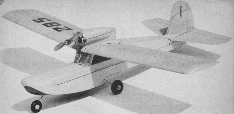
Lower engine mounting and fairly wide hull enables ship
to get off water without help of troublesome sponsoons or
tip floats. Weight is 8 ounces.
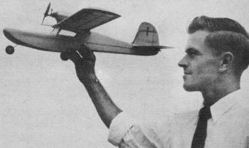
Classy little wagon, we'd say! Hull is given three coats
dope, covered, then three top coats - also three coats inside
cabin. Green and yellow. |
When we just "doodled" the design on a piece of scrap paper, it
was decided that a "trike" gear would be the thing to have, never
giving a thought at the moment to the feasibility of making it work.
After one heck of a lot of head scratching and lost slumber we hit
upon the arrangement shown on the plans. The nose gear (the real
fly in the design ointment) is formed like a bobby pin and pressed
into an aluminum tubing socket that is sewn to the first former.
The main gear is held on the face of the step by three small clamps
and No. 2 wood screws. In this position the ship is rigged out for
land flying. To convert to ROW operation, the nose gear is slipped
out of the aforementioned socket and inserted in the socket shown
in the nose block. The screws in the side clamps of the main gear
are removed and the gear is rotated into the retracted position
shown on the plans. The two small holes in the step can be plugged
by replacing the screws and the main gear is held in the retracted
position with a rubber band. This arrangement overcomes the problem
of severe center of gravity changes when converting from ROG to
ROW and vice versa. The hull is somewhat wider and more
spoon-billed than is normal for a model. This was done in a conscious
effort to eliminate troublesome tip floats or sponsoons. So far,
the idea seems practical, if care is exercised in ROW take-offs.
To increase further the hydro stability, the engine nacelle height
was kept to an absolute minimum, providing only sufficient clearance
for a 6 in. diameter, prop and thereby lowering the CG.
Whether or not the hull design is hydrodynamically efficient is
debatable. A yacht designer friend says it could be improved and
without doubt this is correct. The fact remains, however, that it
works and provides loads of flying fun. The Shoehorn is
designed for .049 to .065 engines. Total weight, ready to fly, should
be approximately 8 oz. Wing span is 32 in.; wing area, 165 sq. in.
The original model is covered with light green tissue, with
yellow trim and black pin striping. So much for the preliminaries.
Let's get on with the main event - building your version of the
Shoehorn. Cut out the sides from medium hard 1/16 in. sheet
balsa. Notice where the sheets are joined together to get the proper
width. Trace the outline of each of the formers on the proper type
of material as indicated on the plans. Cut the formers carefully
and accurately to size.
Mark
the location of bulkheads No.'s 3 and 5 on each of sides and begin
assembly by cementing them in place, paying careful attention to
proper alignment of the sides. After the cement has dried, begin
with former No. 1 and cement the rest of the formers in place.
The 1/8 in. square medium hard balsa stringers are slipped
into the notches in the formers and securely cemented in place.
Sand the corners of the stringers off to fair them in with the slope
of the sides. The top and bottom of the hull or fuselage are cut
from 1/16 thick quarter-ground sheet and carefully cemented to each
former and jointed together along the center stringers.
Cut the stab platform from 1/16 in. sheet and slip it between the
sides and cement in place. The windshield fairing is cut
from 1/4 in. hard sheet balsa and cemented to the front of former
No.3. Trace the nose block side and top outline on a medium
hard balsa block and roughly carve to shape. Spot cement the block
to former No. 1 and carefully carve and sand the block to fair with
the fuselage lines. Pay careful attention to the sweep of the bottom
lines as shown in the side and front views on the plans. The entire
fuselage should be sanded at this point in the construction. Be
careful not to round off the chines (junction of the bottom and
sides); keep it sharp as shown in the former details. Make
up two aluminum sockets from 1/4 OD x 1/32 tubing as shown in detail
by carefully squeezing in a vise. One socket is wired and cemented
to former No. 1 and the other is inserted in the front of the nose
block. Then replace the nose block, cementing it permanently in
place. The nose gear and main gear are bent to shape from
1/16 dia. steel music wire following carefully the outlines shown
on the drawings. Place wheels of the proper size on the gear and
retain by soldering small brass washers to the wire. Make three
small clamps from .010 thick sheet brass by forming it around a
piece of 1/16 wire and squeezing it flat with a pair of pliers.
The main gear is held in place as previously mentioned with three
No. 2 x 3/16 round head brass wood screws. For maximum strength
and watertightness, the fuselage should be given at least three
coasts of clear dope and a final sanding before covering with tissue
or lightweight Silkspan. The covering material should overlap about
1/8 in. at the chines and at the junction of the sides and top.
For maximum strength and toughness the nose block may be covered
with silk or nylon. After covering, the fuselage should get three
coats of clear dope outside and also in the cabin area. The original
was covered with dyed tissue, eliminating the necessity for colored
dope and keeping the weight down to a reasonable figure.
To finish the fuselage, the wing and stab hold-down dowels are
placed as shown and the .010 thick celluloid windshield and windows
cemented in place. The basic wing construction is undoubtedly
"old hat" to all, so we will refrain from any tedious step-by-step
procedure. Instead, let's talk a little about some of the points
that are a little out of the ordinary. Note, during construction
of the wing, that a 1/8 in. space is left between the W-2 ribs to
accommodate the 1/8 in. thick plywood engine nacelle keel. This
unit should fit snugly between these ribs after the leading edge
and center panel have been covered with 1/16 in. soft sheet and
the dihedral formers are in place. Care should be taken during construction
of the wing to align ribs W-2 squarely with the leading and trailing
edges to insure proper alignment of the engine. The sides
of the engine nacelle keel are covered with 1/16 sheet balsa after
it is assembled to the wing. Cheeks, carved and sanded from soft
balsa blocks, plus the 1/8 in. ply firewall are cemented to the
nacelle as shown. The firewall should be drilled for the particular
engine used and may be mounted with small wood screws. If your engine
does not have an integral gas tank, an eyedropper, located as shown,
may be utilized. Some 1/16 in. thick sheet balsa is used
to construct the fairing from the top of the fuselage to the wing
center panel. The wing should be aligned properly and pinned to
the top of the fuselage to insure accuracy between the face of the
fairing and the fuselage. The entire wing assembly should be covered
with dyed tissue or lightweight Silkspan. Six coats of clear dope
will insure a watertight covering job and reduce the weight of the
ship in the long run by reducing the amount of moisture the frame
work will absorb. The rudder and stab are of the simplest
design. The rudder is made of 1/16 thick medium hard sheet, while
the stab is cut from medium hard 3/32 thick balsa. Anti-warp strips,
accurately cut from sheet, are carefully fitted in slots cut in
the rudder and stab as shown and carefully cemented in place. Soft
balsa fairing blocks are cemented to the rudder and stab and carefully
carved and sanded to blend in with the fuselage. In addition to
improving the appearance, these blocks add materially to the strength
of the cemented joint between stab and rudder. The empennage
group, like the rest of the ship, should be covered with tissue
or span and given two coats of very thin dope. The finished
ship should balance on, or very near, the front spar, as shown on
the plans. Any wide variations from this point should be compensated
for by the addition of weight to the nose - or tail, whichever is
required. Carefully sight along the wing and tail surface for any
signs of warping. Any that may be present should be steamed or doped
out before going any farther. Flight testing, to be on the
safe side, should begin by hand gliding into a patch of soft grass.
Adjust wing and stab incidence angles to obtain a smooth straight
glide with just a trace of stall. First power flights, as with glide
tests, should be attempted over land. Initial attempts should be
made with, reduced power, gradually increasing the throttle settings
until full power is attained. Power flight path should be almost
perfectly straight, with a smooth, steady climb. Offset engine thrust
line as required to remove all traces of power turn. At
this point in the flight testing, a little left turn should be added
to the glide path, but not enough to affect powered flight, to keep
the Shoehorn within walking or swimming distance. After the ship
is flying satisfactorily over terra firma, the initial water flights
can be made. The gear should be retracted for all ROW flying
and the ship hand-glided several times to make certain the balance
point has not changed. ROW take-offs require a great deal
of practice and patience but are well worth the effort. If your
Shoehorn has been adjusted properly over land, no trouble should
be experienced on the bounding main. You haven't lived until
you've spent a warm Sunday afternoon flying a hydro job. Try it
and see!
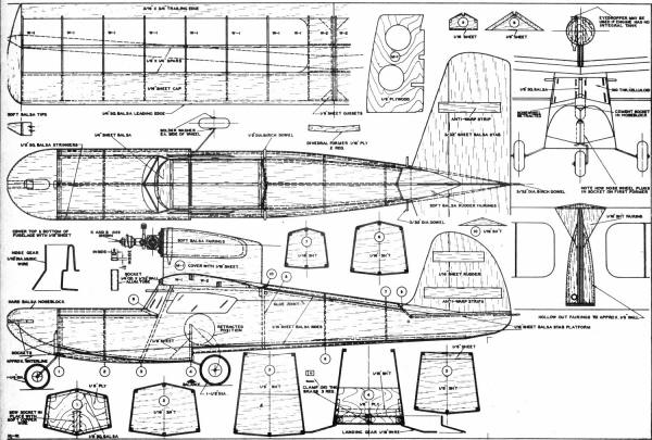
Shoehorn Amphibious Model Airplane Plans
Notice:
The AMA Plans Service offers a
full-size version of many of the plans show here at a very reasonable cost. They
will scale the plans any size for you. It is always best to buy printed plans because
my scanner versions often have distortions that can cause parts to fit poorly. Purchasing
plans also help to support the operation of the
Academy of Model Aeronautics - the #1
advocate for model aviation throughout the world. If the AMA no longer has this
plan on file, I will be glad to send you my higher resolution version.
Try my Scale Calculator for
Model Airplane Plans.
Posted March 9, 2014
|