|
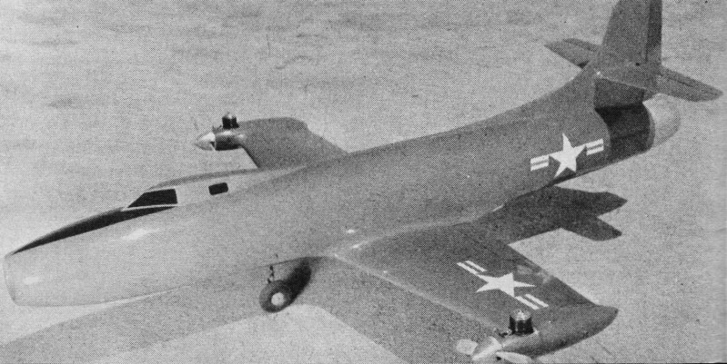
Here is a really unique twin-engined
control line scale model jet. The two 1/2A propeller engines are mounted on the wingtips
where they would be almost unnoticeable as integrated into the tip fuel tanks. Interestingly,
I could not find a single photograph of the Douglas Skystreak with tip tanks. Oh well,
if there ever was one configured that way, surely this is how it would look! According
to designer and author Frank Beatty, his model flies just fine on a single engine, regardless
of whether it is the inboard or the outboard. The wingspan is 43" and fuselage length
is 40 inches.
Douglas Skystreak
Two hot .049's - old Holland Hornet .051's in this case - are adequate
for this 28 1/2" 26 oz. scale model.
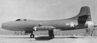
This is the 'real' Douglas Skystreak
How do you make a jet look like a jet in the air - and still have a prop? Use two
props and put the engines in the tip tanks, says this designer. It can be a bit tricky
to fly but offers surprising, and unexplained, benefits!
By Frank Beatty
The air powers of the world began developing experimental jet-powered aircraft for
possible military use during the early stages of World War II. The vastly greater speeds
of these radical new craft posed innumerable design problems, so few of these ships actually
became operational or saw combat service.
Experimental work did not cease in this country at the war's end and the Douglas Skystreak
was developed for the United States Navy to study these transonic speed problems. The
Skystreak, truly a flying laboratory, carried a fantastic maze of instrumentation. For
example, there were more than 400 pressure take-off points located on the wings and control
surfaces alone to accurately measure air pressure distributions on these areas.
Few experimental efforts have been more crowned with success. The Skystreak passed
its Navy acceptance tests in record breaking time, and priceless data were obtained during
its flight test programs. An added bonus was achieved when Major Marion Carl U.S.M.C.,
flying the Skystreak, set a world speed record of 650.92 mph in August 1947.
What ship then could be more appropriate to use in our unusual power plant arrangement
experiment than the experimental Skystreak? But hold on there, why power a scale jet
model in this unorthodox manner to begin with?
The jet age is upon us. We see and admire these sleek craft everyday. Some of the
most beautiful ships ever designed have been jet powered and yet in many years of model
building and flying I can count on my fingers the number of scale jet models I have seen.
Putting it in the old nutshell, few model builders will power a scale model that has
required countless hours to build with a jet engine. The heat insulation problems, brick-heavy
wing loadings, fire hazards and the jet engines' balky starting and running habits discourage
all but the most dedicated. So what is needed is a more reliable method of powering scale
jet models.

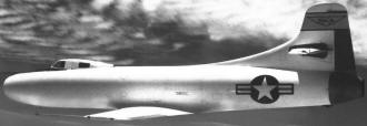
This configuration suggests why Frank's twin has proved such a show-stopper.
Several approaches using conventional gasoline engines have already been successfully
demonstrated. Examples are the ducted fan jobs and the Sabre Stunt. So here is one more
way to fly a scale jet aircraft using the old reliable gas engine. The engines positioned
in the dummy fuel tanks at the wing tips are hardly visible in flight. And think of the
many ships that used tip tanks or armament pods that can be modeled using this idea.
The Grumman Panther, Republic F-84, and many of the Lockheed family including the F-104,
to name a few.
Our Skystreak was selected for its straight-forward lines which would pose no unusual
design or construction problems. The model has been built to a scale of one inch equals
one foot and it spans 28 1/2", is 35 1/2" long and the all up weight is some 26 ounces.
Coloring is bright red with the appropriate national markings and two Holland Hornet
.051's (use any comparable engines) power the Skystreak. Construction is conventional
except for the engine placement - but do study the building and flight instructions;
there might be a helpful hint or two in them! Construction: Start the wings by cutting
out all the parts and making up the sub-assemblies. Cement several widths of 1/16" sheet
balsa together for the wing skins. You will need four sheets approximately 8" wide by
13" long. While these skins are drying, cut out all ribs, tip tank bulkheads, bell crank
mounting plate and plywood wing spar. Drill and groove wing spar for the landing gear
struts and bind these struts to wing spar with thread and cement well. Attach the Hornet
engine mounting brackets (modify mounts according to your powerplants) to bulkheads NI.
Drill 3/32" dia. holes through one of the fuel tanks as indicated. Slip this fuel tank
through bulkhead N2, which has the port wing-tip fuel tank, cut-out and then solder the
tubing line guides into position through the tank. Attach the bellcrank/leadout wire
assembly to its mounting plate.
Cut the bottom wing skins to size and mark all rib, spar and tip bulkhead locations
on these skins with a soft lead pencil. Bevel the trailing edges and drill a small hole
for the landing gear strut to pass through. Cement the spar, ribs, bellcrank assembly
and tip tank bulkheads to the port skin. When dry, cement the leading edge and top skin
into position. Next plank the tip tank area from NI to N3 with 3/32" thick planking strips.
The starboard wing panel can be built in this same manner, with the exception of adding
a 1/2 oz. weight to the tip as indicated. Bolt both engines into place and shape the
various cowling and rear fairings out of balsa blocks, Sand the entire wing assembly
smooth. Brush on two coats of clear dope and fill all pin holes and dents with plastic
balsa. Sand smooth once more and cover with tissue or silk before setting wing aside
for final assembly.
Now
for the tail assembly. Cement widths of the proper thickness of balsa together so that
the vertical and horizontal tail surfaces can each be cut out in one piece. Plane and
sand these parts to shape. Cut the elevators separate from the stabilizer and add the
hinges and control horn. Before installing the control horn use pliers to twist the wire
horn ends to point away from the horn.
The vertical tail surfaces are going to look like a Chinese jigsaw puzzle after we
get through hacking on them. Separate the fin from the rudder, then saw cut outs for
the pushrod and stabilizer. Finally, slice through the parting line so that the stabilizer-elevator
assembly can be cemented into slot, and then cement this rear portion of fin back into
position. Inset the 1/16" plywood bell crank brackets into the lower portion of the fin
and hook up the bellcrank-pushrod assembly to the elevator horn. Fill in the pushrod
slot with the 1/16" sheet fillers and add all fairings. Sand entire assembly well; and
then dope, fill and silk cover as you did the wing.
Cut out all the fuselage bulkheads and keel members. Pin the top and bottom keel members
to a smooth, even workboard surface, and cement all port bulkhead halves and side keel
members into position. When dry, take assembly up from workboard and cement the starboard
bulkhead and keel members into position. Make up the forward landing gear and plywood
mount and cement this assembly into fuselage framework especially well. Add the gussets
to bulkheads #11 and #12 which will help align the tail assembly later on.
The fuselage framework should be strong enough to plank from the top down both sides
without bending or twisting. When all but 1 1/2" of planking at the bottom has been installed,
cement the wing assembly into position. Cut an opening in the fuselage top skin between
bulkhead #11 and #12 and cement the tail assembly into position. After the pushrod linkage
has been hooked up, the remainder of the fuselage can be planked. Sand the planking smooth
and then add the cabin and all fairings or fillets as well as the nose and tail cone
blocks. Sand the entire fuselage smooth and clear dope, fill holes and dents and silk
cover in preparation for finishing the model.
If you plan to install the landing gear doors, cut holes in the wing and fuselage
skins behind where the tabs on the doors will line up. Cement hardwood inserts in these
areas so that wood screws can be used to attach the doors after the model is painted.
The entire model should have been sanded, pin holes and dents filled and sanded smooth
and the entire model covered with silk or tissue, Brush on an additional four coats of
clear dope to seal the silk down tight. Follow this with six or eight coats of balsa
filler coat which has had red dope added to it. Use a fine grade of wet or dry sandpaper
and wets and after every coat of paint throughout the finishing process. When the model
is smooth and the silk pores are filled, spray six to ten coats of Stearman Red on the
model. Rub model down well with rubbing compound. Mask off the various insignia, window
and wheel well openings and spray each of these four coats of dope. Rub these marking
down with extra care as it will spoil a nice finish if you chip the edges or rub through
these markings. Apply the aileron and flap outlines with a draftsman's ruling pen and
thinned out black dope.
Solder the wheels on, attach the landing gear doors with wood screws and cement the
rudder into position with 3/8" offset.
Before the model can be flown, it must be balanced properly. Since there isn't an
engine or other heavy components in the nose, ballast will be required. By installing
a sheet balsa plug and spacers in the nose cone, we create a compartment large enough
to hold the four ounces of lead ballast that is required.
Flying: We naturally chose a calm, windless day for our test flight in order to give
our brainchild every opportunity to prove itself. Light ships with 1/2 A engines like
this are rather sensitive to fly so we quickly discarded our U-Reely handle and switched
to a "half-A handle" and 40-ft. lines of 0.010 diameter cable. And this baby has some
weird flying characteristics, Sometimes when I got a bit careless, I wondered who was
flying whom. But the main points are that a lack of prop blast over the elevator control
surfaces renders them inefficient at low speeds, so allow the Skystreak to build up flying
speed on the ground and haul her smoothly, oh-so smoothly into the air. Maneuvers may
be attempted when full speed is attained in the air! But these are cautious, gentle maneuvers.
This model has no brute of an engine in its nose, so once that massive nose or tail gets
started going in one direction or the other, it is reluctant to change directions again.
But the model is a show stopper. Spectators just don't believe it will fly at all until
they have seen it perform. It has taken off and flown a complete flight on the port (inboard)
engine alone when the outboard engine quit on takeoff on more than one occasion (I don't
understand it!). And it doesn't turn in toward the flyer or go slack on the lines even
though the inboard engine has always quit half dozen laps before the outboard engine
quits. There is little perceptible difference in the airspeed between operations with
either one or both engines running. (Amazing again.)
In retrospect - even though I have never found time for this project - I've often
wondered how a 36-in. Republic F-84 weighing perhaps 2 lbs., similarly powered by two
K&B .15's would perform. Perhaps there will be a reader somewhere who will carry
this experiment a bit further. I'd relish hearing how his experiments turn out.
Douglas Skystreak Plans
Notice:
The AMA Plans Service offers a
full-size version of many of the plans show here at a very reasonable cost. They
will scale the plans any size for you. It is always best to buy printed plans because
my scanner versions often have distortions that can cause parts to fit poorly. Purchasing
plans also help to support the operation of the
Academy of Model Aeronautics - the #1
advocate for model aviation throughout the world. If the AMA no longer has this
plan on file, I will be glad to send you my higher resolution version.
Try my Scale Calculator for
Model Airplane Plans.
Posted May 30, 2015
|