|
If you like cutting and gluing
wing ribs, this scale control line model of the Curtiss P6-E Hawk is the job for
you. Let me know after doing these 92 ribs for two wings if you still feel the same
way. These plans and building article appeared in the November 1957 issue of
American Modeler magazine. Designed for a .19 to .29 engine, this 31" wingspan
model will certainly present a challenge even to the experienced modeler. Of course
you need to be able to apply and finish the covering with a high level of perfection
in order to fully appreciate the amount of work put into building it. Personally,
I would hate to have to use opaque paint for a scale color scheme in order to not
have to hide the framework. Then, I would be afraid to ever fly it!
Curtiss P6-E Hawk for Control Line Fans
Designed and Drawn by Paul Plecan
 For the Flying Scale fan who has a weakness
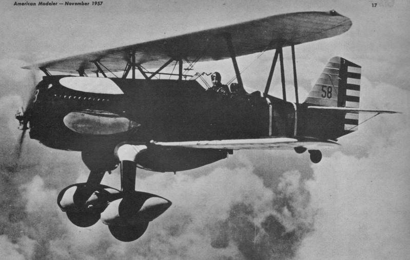
for biplanes, mention of any of the Curtiss "Hawks" brings instantaneous praise.
Rugged, aesthetically pleasing in line and form, almost all "Hawk" models are generously
endowed with the multiplicity of struts, wires, ribs and stringers that set the
"detail hound" to drooling. If you are of this breed, pull up a chair, this is your
meat. For the Flying Scale fan who has a weakness
for biplanes, mention of any of the Curtiss "Hawks" brings instantaneous praise.
Rugged, aesthetically pleasing in line and form, almost all "Hawk" models are generously
endowed with the multiplicity of struts, wires, ribs and stringers that set the
"detail hound" to drooling. If you are of this breed, pull up a chair, this is your
meat.
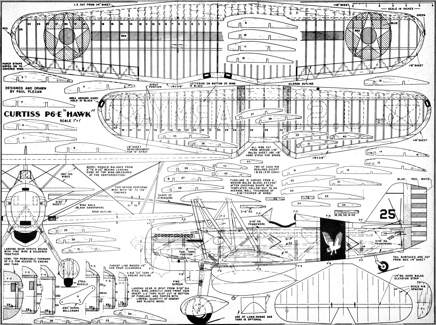
Our model, drawn to a scale of 1" to the foot, performs well with anything from
.19 to .29 displacement, and has scale rib spacing.
Construction is fairly straightforward, but the demands are high if a good-looking
job is to result. After all, with 50 (yes, fifty!) ribs squeezed into 31" of span
for that top wing, each one has to be "right on the button." The examination will
be thorough when the gang spots this job at the local flying site! Built right,
there's nothing like a "Hawk" to command attention, so let's clear the work bench.
Basic framework is 3/16" sq. medium hard balsa as shown in profile view. Not
all framework was shaded in on drawing; to do so would have obliterated other details.
Top longeron is straight (just under stabilizer level); the bottom conforms with
the bottom edge of the profile view. Forward of F-3 these longerons converge, ending
at F-1.
Diagonal bracing is a "must" as is ample drying time for the cement before removing
from workbench for cross-brace installation. Cross-brace sizes are given above cockpit
area. Note two each are required. Since 1B, 2B, 3B and 4B are similar, eight of
this size will be needed. When installing cross-braces, note slight bevels needed
at those ends where the longerons converge aft of cockpit. Those forward of F-4
do not get this treatment.
Once basic framework is built, the balsa-block areas can be worked. Side blocks
cement on first, followed by top and bottom. All cross-sections are on plan. A good
bit of carving is required. Bending stringers to conform with side curves of fuselage
suffice for some modelers, but we think it better to cut out shaped and tapered
stringers as shown (S1 and S2). Then mere application is necessary, plus a bit of
sanding to trim them exactly.
It will be best to "fill-in" the area between stringer S2 and bottom longeron
where lower wing passes through fuselage to obtain strength. Area below stabilizer
is similarly "filled-in," scrap 3/32" or 1/8" balsa being just right. Due to the
taper, the hole in fuselage for passage of wing will have to be large enough for
rib #28 to pass through. After Wing is cemented in place, remaining space is filled
in with Aero Gloss Plastic Balsa or similar compound to produce fillets at root
of lower wing.
Wing construction is orthodox, but take care in cutting out ribs and spars -
in this model, neatness counts. Firm, straight-grained wood is a "must" for entire
wing. For the sake of simplicity, tail surfaces are 1/4 " sheet, sanded to airfoil
(streamline) cross-section. For the rare individual who has all the info on proper
scale rib spacing, etc., the tail can be built up, but it isn't necessary. Scale
position of ribs can be simulated with strips of bond paper cemented to tail where
desired.
Individual ability will be governing factor in the completion of model, as will
the amount of extra detail over and above that shown on plans. Correct information
on coloring is a stumbling-block for many, so here is the data for your P6-E: fuselage
was olive drab, although just prior to WW 2, some P6-Es had blue. Nose area, L.G.
struts, hawk talons or claws on the wheel-pants, and band around rear of fuselage
was black. White trim as shown. Hawk on each side of fuselage, white. Wings entirely
yellow, except for national insignia and red stripe on top wing; black lettering
and national insignia on lower wing (bottom surface only). Hand-holds on lower wing
tips and center section of upper wing are black.
Horizontal tail surface entirely yellow, same for fin and that portion of rudder
ahead of the hinge line. Red, white and blue striping on rudder as indicated on
plans. White diamond trim on headrest. Black number on fin; same number in white
on nose just above prop. These markings are those used by 17th Pursuit Squadron
based at Selfridge Field, Michigan, in mid-thirties.
Minor variations occurred in many P6-E Hawks. Wheel-pants that exposed the outboard
face of wheel appeared on later versions in interest of faster wheel-changes or
tire repairs. While enclosed cockpits and supercharged engines were also used, it
is doubtful if these changes saw actual squadron service.
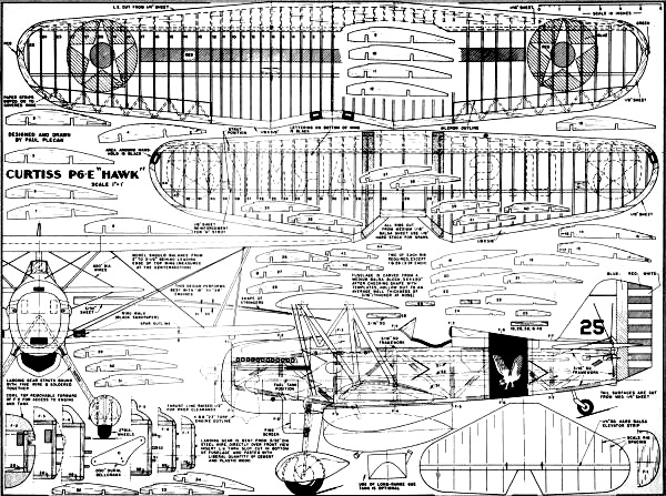
Control Line Curtiss P6-E Hawk Plans
Bill of Materials
(Balsa, unless otherwise specified)
Five pieces 1/16" x 2" x 36" for ribs, leading edge covering; (1) 1/8" x 2" x
36" for spars, wing tips, etc.; (2) 1/8" x 3/8" x 36" trailing edge stock; (6) 3/16"
x 3/16" 36" hard balsa for longerons, cross braces, etc.; (1) 3/32 x 2" x 36" for
stringers, fill-in material; (1) 1/2" x 1 1/4" x 3" nose block; (1) 1" x 2 3/4"
x 14" turtledeck; (1) 7/8" x 2 3/4" x 5 3/8" top-front cowl; (1) 1" x 2 5/8" x 5"
bottom cowl; (2) 3/8" x 3" x 5 1/4" side cowls; (1) 1/4" x 3" x 36" medium for tail
surfaces (use leftovers for wheel-pants, etc.); (1) 3/32" x 1/4" x 30" N-struts
(pine or other hard wood); (1) 3/32" x 5/32" x 20" cabane struts (pine); (2) 5/16"
5/8" x 5" hard wood engine bearers; (1) 3/32" dia. x 36" steel wire for landing
gears; (1) 2 1/2" bellcrank; (1) .045" or .049" dia. x 36" steel wire for pushrod;
(1) 3/4" dia. tailwheel; (1) pair 2" dia. main wheels; (1) 3/16" dia. brass or aluminum
tubing for scale exhaust stacks; (5) .020 dia. steel wire rigging; dope, cement,
Aero Gloss Plastic Balsa as required; engine .23 cu. in. displacement (or close).
tank, fuel line, props, related flying equipment as required.
A few remarks concerning biplane U-control models will not be out of place here.
Incidence of wings is of utmost importance - making a simple scrap "jig" to position
upper wing is mandatory when struts are being cut to size and fitted. Strength of
joints where struts join fuselage and where they meet wing surface is very. very
important ... you don't want the upper wing to part company with its mate on a rough
landing. A free-turning pair of wheels is necessary, since model sets higher off
ground than a monoplane. Be ready to trot forward the moment the wheels touch down,
so model rolls straight ahead with your control lines loose.
Notice:
The AMA Plans Service offers a
full-size version of many of the plans show here at a very reasonable cost. They
will scale the plans any size for you. It is always best to buy printed plans because
my scanner versions often have distortions that can cause parts to fit poorly. Purchasing
plans also help to support the operation of the
Academy of Model Aeronautics - the #1
advocate for model aviation throughout the world. If the AMA no longer has this
plan on file, I will be glad to send you my higher resolution version.
Try my Scale Calculator for
Model Airplane Plans.
Posted December 8, 2021
(updated from original post on 5/3/2014)
|