|
This is the prototype of American Aircraft Modeler's "AAM
Glowdriver." To be more accurate, the experimental construction
is on an actual wooden breadboard - the kind used in a kitchen-
making it in fact a prime example how the term "breadboard" for
electronic circuit construction came to be. There is also an accompanying
article in the same July 1974 edition titled "Fast
Start Set Uses the AAM Glowdriver." Thanks to Danny M.,
a website visitor from The Land Down Under, who wrote to ask that
I scan and post this article for what today we would call a 'smart'
glow plug driver."
The AAM Glowdriver
Here's a gadget that takes the sense of accomplishment out of
starting your engine.
By C. W. MCCutchen
|
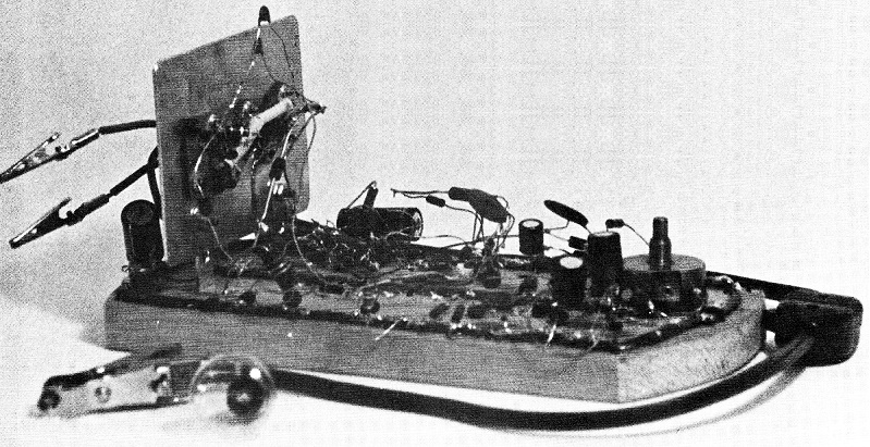
The prototype AAM Glowdriver. When the author said
that he had one roughed out on a breadboard, he wasn't kidding
- it's on an honest-to-goodness board for cutting bread!
The accompanying article by Hobie Steele tells how to build
a neat, compact version.
|
Starting a model engine is a test of skill. The biggest problem
is drowning the glow plug with fuel. A flooded plug gives no ignition.
Afraid of the resulting silence, one tends to under-prime, and get
silence anyway. The AAM Glowdriver clears a drowned plug in a fraction
of a second. With ignition guaranteed, a big shot of fuel may be
applied through the exhaust port - no more fear of over-priming.
All engines tested so far have started with a few flips of the propeller
- even in freezing weather.
The AAM Glowdriver ends the minor worries, too. It will heat
the plug all day long (a month or more of steady flying) on a single
charge of its 12 volt motorcycle battery. It tells if the glow plug
is burned out, and it warns, hours in advance, that the battery
is weakening. There is no battery drain when the unit is not connected
to the plug. Except in one important way (see below), the Glowdriver
is used just like a clever battery.
It heats the glow plug with current pulses of variable length
(about 13 milliseconds apart). During each pulse, the potential
across the plug and leads is about eight volts. The current through
the plug is ten amperes, more or less, depending on the resistance
of the plug. As the Glowdriver heats the plug, it simultaneously
measures its temperature. It then automatically adjusts the length
of the current pulses, to bring the temperature to the right value
for guaranteed ignition.
The prototype AAM Glowdriver. When the author said that he had
one roughed out on a breadboard, he wasn't kidding - it's an honest-to-goodness
board for cutting bread! The accompanying article by Hobie Steele
tells how to build a neat, compact version.
When the plug is fuel-soaked, the current pulses are up to six
milliseconds long. The fuel near the hot element boils so violently
that the excess fuel is immediately expelled. As the plug warms
up to its normal temperature, the length of the current pulses drops
to about .2-.5 milliseconds, depending on the type of plug.
The heating current is switched on and off by the power transistors
X5 and X6, under control of their driver (X4). This, and the string
of emitter followers, X1, X2 and X3, form one half of a multivibrator,
which times the current pulses. The other half of the multivibrator
is X7.
The resistance of the glow plug rises as its temperature increases.
To measure its temperature, we measure the resistance with a Wheatstone
bridge (the circuit to the left of X8 and X10 in the drawing). Bridge
unbalance changes the potential between the base and the emitter
of X8. If the glow plug is too hot, the current through X8 is larger
than it ought to be. This current is amplified by X9. The amplified
current speeds the discharge of the .47 microfarad C2. In this state,
X7 is cut off, which shortens each pulse of heating current, and
returns the glow plug to the right temperature. The temperature
is set by the 500 ohm potentiometer.
|
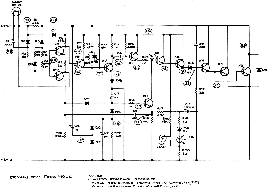
The AAM Glowdriver schematic.
|
If the glow plug is too cold, X9 feeds less current to the capacitor
C2, and the pulses are longer. When the plug is extremely cold,
X9 is cut off, and the capacitor is discharged only by current through
the 15 kilohm resistor. This gives the maximum pulse length, six
milliseconds,
The current to run all parts of the circuit comes through the
glow plug, and stops entirely when the plug is disconnected. Except
during the heating current pulses, the circuit draws less than 50
milliamperes, which causes negligible potential drop across the
plug. During the pulses of heating current, when the potential drop
across the plug and leads is eight volts, the diodes D1 and D2 (above
the bridge) cut off. The circuit then coasts on the charge stored
in the two 1000 microfarad capacitors, C1 and C7.
X10 and X11, and their associated components, cut off the current
if the plug lead is shortened. They keep the plug from being overheated
by multiple illegitimate pulses at the moment the connection is
made and broken. The mini-lamp is a pilot light. It goes on whenever
current flows through the glow plug lead. The light emitting diode
tells the state of charge in the battery. Its brightness falls sharply
as the battery discharges, and it goes out when only a couple of
hours of operation remain. When both lights are out, either the
battery is truly dead, or the glow plug is burned out or badly connected.
To identify the trouble, one can short circuit the glow plug connector.
The incandescent bulb will come on if the battery is live. Glowdriver
will work without this luxury feature, since a faint buzzing noise
tells when it is supplying current.
In Use
Because different glow plugs have diverse resistances at operating
temperature, they may require different temperature settings, even
though their operating voltage may be the same. Here the AAM Glowdriver
is not like a battery! With an unfamiliar glow plug, start with
the temperature control at its coldest (the plug out of the engine).
Connect the plug, and raise the temperature control until the plug
has the right color. I find that Cox 010, 020 and 049 coiled wire
plugs can all be run at the same setting, but may burn out on the
setting that runs a Fox Standard plug. The component values in the
bridge were chosen to cover all the glow plugs I could find, from
the lowest resistance to the highest. To extend its range in the
cooler direction, lower the value of R2; in the hotter direction,
lower R4.
To start an engine using the Glowdriver, set the needle valve
according to the manufacturer's instructions. Prime the engine generously,
preferably through the exhaust port, and flip the propeller until
it starts. Remember the part about the needle valve. Do not make
sure that you have enough fuel in the cylinder by opening the needle
valve way up. Neither Glowdriver, nor anything else, can burn a
never-ending stream of fuel. Because Glowdriver prevents plug drowning,
one may still get occasional firing, and not realize that the mixture
is too rich.
If you do not know the right needle valve setting, start with
it lean and prime heavily. The mixture must pass through the right
value in its progress from too lean to rich. With the AAM Glowdriver
keeping the plug dry, the engine will run at least briefly, and
you can open the needle valve a bit and try again.
Even inverted engines start easily with the AAM Glowdriver. After
flooding my inverted OS Max 10 RC intentionally, I found that it
will start in less than fifteen flips. Sometimes, one flip is enough.
If you must start your engine in one second, rather than five, you
can use an electric starter along with Glowdriver. The OS Max 10
RC and a Webra 60 both roar to life the instant the starter hits
the spinner.
Electric starters pull down the battery voltage, and some of
them make it very uneven. The glow plug will probably heat up or
cool down a bit while the starter is running, but not enough to
cause trouble. If the plug gets very hot and threatens to burn out,
X7 probably has much less than its proper current gain, and should
be replaced.
Glowdriver is great for the hydro modeler. A drowned engine can
be running in less than a minute, without removing the glow plug.
First, refuel under pressure so as to flush any water in the tank
and fuel line out through the needle valve. When the fuel that drips
out of the needle valve is clear, this purging is complete. Prime
generously through the carburetor, to dilute the water in the crankcase.
The engine will give isolated explosions almost immediately. After
a couple of dozen revs, it will either start, or run for a burst
and then stop. In the latter case, priming again through the carburetor
will do the trick.
Troubleshooting
Each of my Glowdrivers has also had at least one wiring error.
All required some troubleshooting before they ran properly. Except
for the high power transistors X4, X5 and X6, the use of hobby grade
components has resulted in some defective items.
The wires, shown as bold lines in the drawing, carry the pulses
of heating current. Make them no thinner than No. 18 wire, so as
not to have unwanted potential differences between one part of the
circuit and another. For connecting Glowdriver to the battery and
to the glow plug, household lamp cord is satisfactory (not more
than 8 feet). If you want to run Glowdriver with 50 foot leads from
your car battery, use heavier wire.
Here, an oscilloscope is a great help. On one Glowdriver, I got
rid of the bugs with only a voltmeter, to show that it could be
done. The numbers in ovals in Figure 1 are voltages at the various
points, relative to the negative buss. Readings are taken with the
filament of a Fox Standard glow plug, or an 1133 light bulb, bright
orange. Because troubleshooting can be expensive in glow plugs,
I use a number 1133 six volt bulb as a dummy plug. It draws about
the same current.
If the test bulb fails to light, even when the temperature control
is wound to maximum heat, put it to your ear and listen. If it is
going "ping-ping-ping," the anti-short circuit is firing and keeping
the current shut off. This can happen if you start with the temperature
control set high. The resistance of the cold bulb is so low, compared
to what Glowdriver expects, that it thinks the bulb is a short circuit.
Turn the temperature control down to the bottom and bring it back
up. If the bulb lights, the multivibrator is working and all is
well. You can confirm this by listening to the bulb. It will be
singing continuously from the multivibrator pulses. If, instead,
the bulb continues to go "ping-ping-ping," you are on your own.
This has never happened to me. If it did, I would check the wiring
of the bridge, because X10 must be getting the wrong input.
If the bulb fails to light and makes no noise at all, check that
the electricity is actually reaching the timing circuit and the
transistors X4, X5, and X6. There should be about twelve volts across
each. If the circuit is correctly wired, the pilot light should
light. If there are no volts, disconnect Glowdriver from the battery,
and use an ohmmeter to locate the break in the circuit. To check
the forward conduction of D1, or any other diode, the ohmmeter must
be applied the right way round. In both of my ohmmeters the positive
terminal on ohms only is black. To check yours, set it to ohms and
charge a large capacitor with it. Then put it on the five to ten
volt scale and connect it again to the capacitor. The direction
of the kick tells the sign of the charge on the capacitor.
AAM's Editor gives McCutchen's original AAM Glowdriver (a genuine
Joule box) a try on an inverted, cowled engine. It started consistently
(about a dozen times) on the first flip.
If the circuit has volts on it, and the bulb still will not light,
check the potentials between base and emitter of transistors X2,
X3, X4, and the pair X5 and X6. If any base-emitter potential is
much bigger than .6 volts, replace the transistor. Likewise, the
Zener should have four volts across it, and the 1K resistor less
than one volt. If the resistor has much more than this, disconnect
X11 from X2, or remove X11. If the bulb now lights, the trouble
is with X11 or the circuit that runs it. See if the potentials in
the circuit match those in the diagram. If they do, X11 is shorted
and should be replaced. If they are wrong, find out why. The circuit
is simple enough, so it is not hard to run down the faulty component.
If the light lights like a photoflood, X7 is probably dead or
miswired. If the wiring is right, yet the collector potential is
about 12 volts, replace X7 and all should be well. If the light
sings, but lights brightly and cannot be turned down by the temperature
control, there is trouble with the bridge, with X8 or with X9. Voltage
measurements do not help much here, so check the wiring, and if
you do not find the cause there, replace the transistors.
If the bulb flares up briefly as it is connected and disconnected,
the anti-multipulse circuit is not working. Check the potentials
on X11. If they are wrong, find the bad component in the diode pump
(C4, D6 and D7). If, when the glow plug connector is short circuited,
it makes a heavy buzz, rather than a slow "tick-tick-tick," verify
that the anti-multipulse feedback is working. If it is, then X11
is good, so the trouble must be in X10, or diode D4, or (less likely)
capacitor C8.
If these procedures do not find the trouble, something mysterious
is happening, and you need a friend with an oscilloscope. The surest
procedure is then to lift the collector of X11 from the base of
X2 and connect it to the positive buss, via a 1K resistor. Also,
lift the collector of X9 from the base of X7 and connect it to the
negative buss, via a 39 ohm resistor. This isolates the temperature
control feedback, the anti-multipulse and anti-short circuit feedbacks
from the multivibrator. We can now examine the feedback signals.
A further trick is to insert a 3.3 ohm resistor between the collector
of X3 and the positive buss. The signal across this resistor should
start at about 1.5 volts, implying .5 ampere of the drive current
through the Zener to X4. This will fall with time, as the current
pulse proceeds.
If you are an experimenter at heart, build Glowdriver on a breadboard.
It takes an evening, if you are not fussy about appearance. For
a rugged, professional looking job, read the next article, where
Hobie Steele tells how to make it as a printed circuit.
Posted June 28, 2014
|