|
Nearly two years ago I scanned
and posted just the plans for the Martin MO-1 control line model intended for Navy
Carrier events, but I did not post the construction article. So, I finally added
the article for you. Here are plans for the Martin MO-1 that I electronically scanned
from my purchased copy of the August 1969 American Aircraft Modeler magazine. To
this day, the MO-1 is the preferred model for the event. It will be interesting
to see how the AMA's adoption of new rules for control line competition that allows
radio control of any function other than elevator control will affect Carrier competition.
I foresee gyroscope stabilization and airspeed hold functions. Plans for this fine
model were drawn by Don Gerber and Charles Reeves. All copyrights (if any) are hereby
acknowledged.
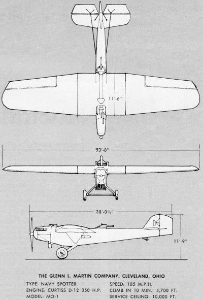
"The Martin MO was an American observation monoplane built by the Glenn L. Martin
Company of Cleveland, Ohio for the United States Navy." -
Wikipedia
The Martin MO-1 is widely used in the AMA's Navy Carrier event.
See "Portable
Control Line Aircraft Carrier Deck" (March 1962 American Modeler), "Livingston
(NJ) Club Builds Carrier Deck" (September 1967 American Modeler), and "Flying
the Carrier Event" (July 1951 Air Trails).
Martin Mo-1
The first all-metal plane designed and built in the U. S. Extremely
rugged, with a high-lift wing, it was shipboard operated.
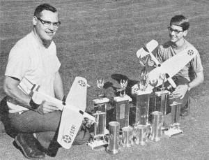
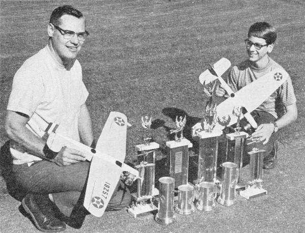
The winning records with the MO-1 were set by Don Gerber and
son, John, in both Class I and II Navy Carrier. Difference between Classes is use
of 40- or 60-size engine.
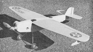
Important features here: adjustable leadouts and hinged ailerons
instead of flaps.
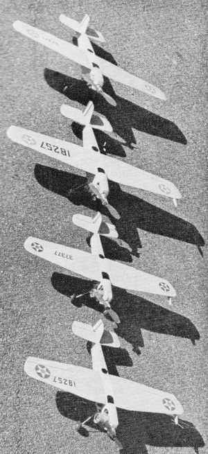
Rossi 60 speed and K&B 40RR engines set up by Bill Johnson,
known as "Throttle Man."

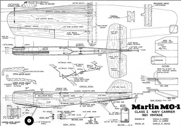
Martin MO-1 3-view
A vintage aircraft's functional design is the basis for this Junior-age-class
record setter.
Don Gerber and Charles Reeves
One of the most rewarding aspects of this hobby is the designing of a model and
then following through with the building, perfecting, flying, and winning with this
aircraft. I tremendously enjoy flying in competition and am always looking for something
different, something original that I can call my own.
While going through the books in a library 400 miles from home, I found the first
bit of information which led to the design of this model. The book, "Airplanes of
the World - 1490-1962" by Doug Rolfe and, of all people, Bill Winter, showed a small
drawing of the plane, and gave the information that the MO-1, designed in 1921 as
a shipboard observation plane, was the first all-metal plane designed and built
in the United States. The word "shipboard" was all the incentive that I needed.
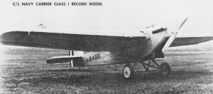
During the summer of 1967 I corresponded with the Martin Marietta Corp. and got
a photograph of the real plane and a good three-view drawing. Invaluable was the
letter from Martin Marietta verifying the MO-1 as being carrier-based: "In response
to your request for verification of the use of the early Martin-built MO-1, our
records indicate that this plane was carrier-based along with the bombing and torpedo
squadrons of the U. S. Navy in 1924, but was classed as a light-weight scout monoplane."
With this information I drew the first set of crude plans. Later that fall I
started corresponding with Mr. Don Gerber of Laureldale, Pa., who was the current
class I record holder. Since he was interested in the model, I sent him a copy of
the information that I had, and a rough copy of the plans I had drawn. That winter
he redrew the plans in detail, developed construction techniques for both class
I and class II versions of the MO-1. He and his son (John) built several of the
planes of both classes. The contest record of their MO-1s during the summer of 1968
is phenomenal. They had a total of six first-places, five second-places and one
third-place, and these include the AMA class I and class II junior records and a
first-place win in junior class I navy carrier at the 1968 Olathe Nats for John
Gerber. They had done all this, and I hadn't even started construction on mine.
I should make it clear that this is a joint article presented by both myself
and Don Gerber, and that Don should receive the lion's share of the credit for developing
and testing the model.
If this plane doesn't convert a few of you rat race racers to navy carrier, then
you just can't be converted, because it sure has the looks of a good, clean rat
racer. The construction is similar too, with the exception of the metal pan used
on most rats today.
Start construction with the solid wing by gluing the 3/8" redwood leading edge
to the balsa plank and working down the wing with a razor plane to the airfoil shape
shown in the fuselage side view and the wing tip section. Make sure the wing center
section bottom is flat, out to the point where the leading and trailing edges begin
to taper, and then works to a symmetrical section at the tip. Don't cut out the
ailerons until the wing has been completely shaped and sanded. Notice I said "ailerons"
and not "flaps." The MO-1 had no flaps, so the ailerons are used as ailerons during
low speed to bank the model toward the outside of the circle and hold the lines
tight.
At this point it would be good to make all the assorted hardware, such as the
aileron horns (which I found to be easy to make from mild steel welding rod material)
the aileron transfer horn, the arresting hook and tail skid on their plywood mount;
the main landing gear on its plywood mount, the fuel tank, firewall, bellcrank mount
leadout guide, and motor mounts.
Some of the special construction techniques developed by Don for this model are
now apparent. His first MO-1 had a solid balsa wing which failed in flight, so the
redwood leading edge was incorporated to strengthen the wing. Special motor mounts
were needed to tie the nose to the wing to eliminate a stress crack in the fuselage
at the wing leading edge, so mounts were laminated from birch plywood to tie together
the wing, bell crank mount, firewall, landing gear mount, and the fuselage bottom.
Also the top block on the nose was changed from balsa to bass and extended back
over the leading edge of the wing. Oh yes, the motor had to be moved as far forward
as the nose would allow to keep the center of gravity in a decent location and since
it has been mounted in a sidewinder fashion like on a combat plane, no outboard
tip weight is required.
One word about the control unit and then we'll continue with the construction.
The bellcrank is the J. Roberts inverted unit with the bellcrank cut to 2 3/8".
These can be purchased from Sturdi-Built, or you can get the custom assembled unit
from Bill Johnson, the "Throttle Specialist." Bill's units are made from Sturdi-Built
parts, but because he only does custom work, he can get a better fit and smoother
operation. All his units are assembled with countersunk rivets, which adds to their
safety factor. I also recommend the use of his fuel metering system which allows
the hottest of racing engines to be run on pressure and yet to be throttled like
the best R/C engine. The single throw set-up for the exhaust slide and fuel meter
is also available from him by ordering the Don Gerber MO-1 single throw modification.
Now that most of the small details have been discussed, let's start assembling
these little parts together to make an operating model. Cut out the ailerons, shape
their leading edge, glue the horns to them, and hinge them to the wing with the
horns running through the slots in the bottom of the wing. Glue the cap strip over
the slots and the lead out guide to the inboard tip, and the wing is finished.
To start the fuselage construction, drill the motor mounts for the mounting bolts
and bolt the motor to them using blind mounting nuts. Then glue in the firewall
and main landing gear. Next, mark the centerline on the bottom of the wing and glue
the wing to the motor mount unit making sure to align the motor mount and wing centerline
perfectly. Attach the leadouts to the bellcrank, bolt the unit to the plywood bellcrank
mount, and glue the whole unit to the bottom of the wing with the bellcrank hanging
down. This will go right around the motor mount.
Cut out two identical fuselage sides and glue the tank to the inboard side. That's
right - glue it on! Add filler blocks between the motor mounts and the fuselage
side, and glue the inboard fuselage side to the motor mount-wing-landing-gear unit.
Make the elevator pushrod long enough to reach to the vicinity of the elevator horn
and attach it to the bellcrank. Also, make up the throttle pushrod and run it to
the engine. This has been omitted on the plans because of the many types of throttles
that can be used. Install this to suit the type of throttle that you are using on
your engine. After this has been installed, the engine should be removed, filler
blocks added to the outboard side of the motor mounts, and the outboard side of
the fuselage glued on.
Shape the rudder, stabilizer and elevators hinge the elevators, and glue these
together as a unit. Now position the stabilizer on the rear of the fuselage, adjust
the pushrod to the correct length, and glue the unit to the fuselage, pulling the
rear end of the fuselage together at the same time.
The arresting hook and tail skid unit can be installed along with the rest of
the aileron linkage. The spring should be just strong enough to pull the hook down
and deflect the ailerons, but not strong enough to flip the plane up on its nose.
With the addition of the fuselage planking on the top and bottom, this thing finally
looks like a plane. But wait, it doesn't have any motor now! You took it out. Remember?
Build a removable cowl section into the outboard side of the nose. This should be
just large enough to get the motor in and out, and to get to all the plumbing and
throttle linkage required for your engine.
The finish consists of two coats of clear dope lightly sanded, one coat Hobbypoxy
Stuff wet sanded, and one coat of Hobbypoxy color sprayed on. The color scheme is
gray fuselage and wing and stab bottoms with yellow wing and stab tops. With red:
white, and blue stripes on the rudder, and the white star with red center on a blue
circle on the top and bottom of each wing, it makes a colorful little plane. The
total weight should be 24-26 ounces. With this lightweight and small size, the MO-1
is a real competitor, so why don't you build one and compete?
Martin MO-1 Navy Carrier Control
Line Plans <click for larger
version>
Notice:
The AMA Plans Service offers a
full-size version of many of the plans show here at a very reasonable cost. They
will scale the plans any size for you. It is always best to buy printed plans because
my scanner versions often have distortions that can cause parts to fit poorly. Purchasing
plans also help to support the operation of the
Academy of Model Aeronautics - the #1
advocate for model aviation throughout the world. If the AMA no longer has this
plan on file, I will be glad to send you my higher resolution version.
Try my Scale Calculator for
Model Airplane Plans.
Posted February 3, 2013
|