|
The Douglas DC−3
(C−47 was the military version designation) has always been my favorite twin
engined commercial airplane. Its nickname of "Gooney Bird" amongst troops is
undeserved IMHO. The DC−3 is credited with launching the commercial airline
industry, and its C−47 version was listed by Dwight D. Eisenhower as being on
the most important tools for winning World War II. Edward F. Burton, Chief
Engineer at Douglas Aircraft Company, runs through the evolution of the DC−3 and
it predecessors and descendants in this December 1945 issue of Flying Age
magazine. December of 1935 marked the maiden flight of the DC−2, was was a
direct follow-on the the DC−2. A single DC−4 (4 engines) was built and delivered
to Japan. Then a DC−5
was built (high-wing version of the DC−3) but never went into production. The
4-engine DC−6 entered commercial
service in 1946, followed by the very popular
DC−7. A coaxial,
counter-rotating pusher prop model
DC−8 (not to be confused with the 4-engine
commercial DC−8 jet) never made it
off the drawing board. The next iteration was the C−54, which was a huge success
with four engines and tricycle landing gear. It became the first dedicated
presidential aircraft (aka
Air Force One). Finally (at the time of this "Build Me a Plane" article),
the C−74
Globemaster made its debut in September of 1945, right after World War II
ended.
Build Me a Plane
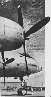
The power and the beauty of the Globemaster has a history of
patient endeavor and a series of experimental predecessors that paved its way.
It takes years of patient, skilled, heart-breaking man-hours to evolve a plane
that will do its job.
By Edward F. Burton
Chief Eng., Douglas Aircraft Co.
No airplane is ready-to-wear. They're all custom-made to some pretty exacting
requirements.
When you buy your ticket, walk up the gangway and say "hello" to the hostess,
you take your airplane for granted. It will fly to the precise destination you want
on a schedule neatly predicted. There will be a seat that can he inclined at a proper
napping angle. There will be ventilators that you will manipulate without a second
glance. There will be ash trays at your hand.
But most thoroughly taken for granted of all the airplane's many qualities is
that it will fly. And what is more important it will have the flying characteristics
most needed on the particular route you must take. In short, it fits precisely.
And the story behind that perfect fit is one of meticulous planning, of countless
highly skilled man-hours, of tests, failures and a success that is cumulative, growing
out of all the previous successes and failures in the business.
The airlines know, or think they know, exactly what the passenger and the cargo
shipper want on any particular hop. And they come to the aircraft companies with
a list of requirements. We must have so much room for cargo, they say. We must have
so many passengers, and this percentage of them must have berths. We must be able
to feed them. The crew must have quarters. Then, it will have to go at this speed,
have that cruising range, be able to fly in weather like this or that. There's what
we want; they conclude, go build us a plane to do the job cut out for it.
And the aircraft companies examine the list of requirements, go over all the
blueprints of previous planes, acknowledging this factor and deciding to reject
that one.
A case in point is the DC-8, Douglas' latest model which with its dual props
in tandem right behind the tail, promises to create a stir in engineering circles
and in air passenger circles. But it is really a product of all that went before
it. It is the final phase in a development that began with the DC-1 back in 1933.
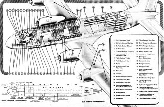
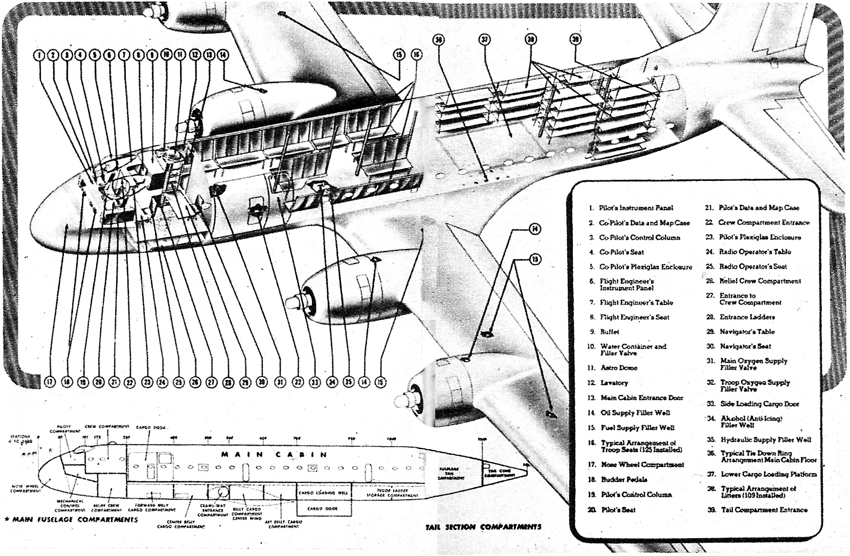
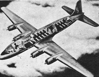
The Globemaster's interior. Planned as a troop transport, C-74,
holds 109 wounded patients on litters or 125 troops in seats. Crew facilities remain
similar in the civil version.
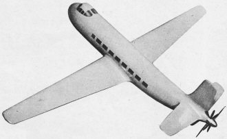
Model of original DC-8 with counter-rotating propellers.
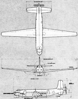
Driven like an ocean liner with two counter-rotating props in
tandem at tail is the DC-8, forty-eight passenger transport planned by Douglas.
Shown above is three-view and model.
The DC-1, which cruised on its two Wrights at 170 miles an hour, was the first
twin-engine airplane capable. of flying and climbing with a full load on only one
engine. This airplane also had retractable landing gear, but it was not entirely
enclosed, It was this ship that the late Eddie Allen, during a test flight prior
to its public appearance landed with the gear retracted. Eddie's only comment on
debarking was, "Oh, for pity's sake!"
Before the DC-1 flew, however, much of the basic research from which all our
transports have developed, was completed. Aerodynamic calculations were particularly
concerned with performance and control at all attitudes of flight, both in normal
and single-engine operating conditions. Special designs of the controls, wing, and
fairing made possible continued, single-engine operation at high altitudes with
sufficient controllability to insure safety in meeting emergencies. Performance
studies to obtain the desired velocity, range and climb led to the choice of the
bi-motor type with controllable pitch propellers and high-lift wing flaps. The flaps
gave a gain in lift of thirty-five percent, and a drag increase of 300 percent.
Three complete wings were tested with various modifications of fuselage fillets,
tail surfaces, landing gears and tail wheels. Several sets of ailerons of normal
and special types, six arrangements of high-lift flap devices were among other special
arrangements tried.
Some of the early models tested in the wind tunnel showed instability and tests
revealed that it was necessary for satisfactory stability to have a hitherto untried
arrangement of center of gravity, wing sweepback and general configuration. The
actual airplane was built in accordance with this new plan and its stability in
flight proved to be exactly as predicted. Had not the wind tunnel tests been made,
it is possible the DC-1 would have proved unstable, since ordinary investigation
had indicated the original arrangement would be satisfactory.
As one result of these tests and changes, the total resistance of the complete
airplane was less than twice the resistance of the wing alone!
Wind tunnel tests indicated the best aerodynamic arrangement, but did not determine
the location and proportion of all structural details. To work it all out, we constructed
a mockup with wooden frames, covered with heavy paper to stimulate the metal sheet
covering. All frames were made in the exact sizes and locations of those in the
actual airplane. A complete floor was installed and various seating arrangements
tried to obtain maximum roominess and comfort. Final arrangement placed each passenger
chair opposite a window, gave' ample leg room, wide and unobstructed aisles, and
allowed a passenger over six feet tall to walk erect in the cabin. Many designs
of passenger chairs were tried before we finally chose an aluminum alloy structure,
so designed that the angle of inclination of the entire seat could be changed and
the back adjusted for sleeping. The seat was also reversible, permitting passengers
to face either forward or to the rear. This was the beginning of passenger comfort
in the air.
As for structural development, the studies of aerodynamics and general arrangement
showed the desirability of having the engine nacelles well ahead of the wing's leading
edge, a practice later found even more necessary on larger aircraft. It was also
found desirable to house the retractable landing gear within the nacelles. With
these points in mind, it was then necessary to develop maximum strength and rigidity
with minimum weight. Therefore, we designed a wing with the material so distributed
that there was little variation in the stresses of the various parts. At the same
time, the wing proved to have little or no torsional deflection, a minimum of vertical
deflection, and no excessively large unsupported flat metal surfaces.
In a metal wing, having a thin skin rigidly attached to a heavy spar, sudden
changes in cross section are apt to cause objectionable stress concentrations. Other
dangers exist as well. In seeking the answer to this problem we considered single,
two, three and multi-spar designs, as well as shell type and multi-cellular designs.
We finally decided upon the Northrop multi-cellular wing, a type we have employed
throughout all Douglas transports. This type of structure consists of a flat skin
reinforced by numerous longitudinals and ribs. Because the major loads are carried
in the outer surface of the wing as well as in the internal structure, inspection
of the exterior gives a ready indication of the structural condition.
In the fuselage, the structural problem was basically the same. This construction
consists of a smooth, stressed skin in contact with closely spaced over-strength
bulkheads and numerous longitudinal stringers. All parts are securely attached together,
and the skin has very small unsupported areas.
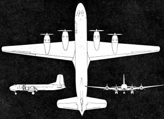
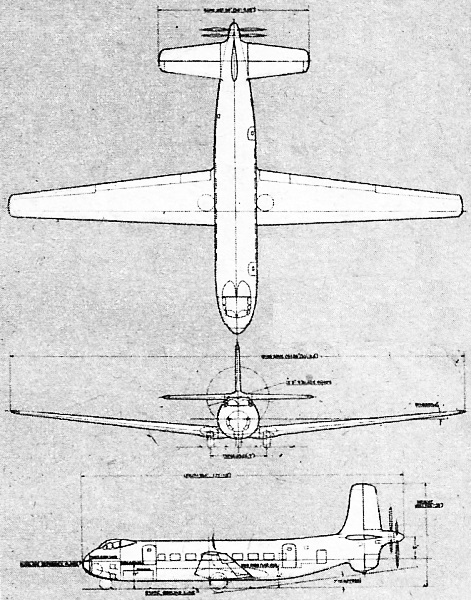
Three-view of the Globemaster.
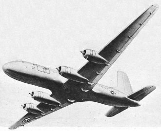
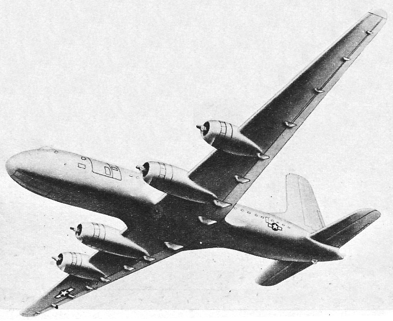
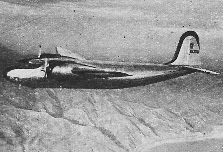
Artist's drawing of the Globemaster. Other DCs led up to it.
Twelve passengers flew in the DC-1, and fourteen flew in the DC-2, which appeared
in 1934. The DC-2 was little more than a slight re-design of the DC-1. It really
was the production version of the experimental DC-1. The DC-2's fuselage was forty
inches longer to increase passenger capacity and assist in balance control.
Two years later the DC-3 appeared. This airplane, a real contribution to low-cost
travel, accommodated twenty-one persons in seven rows of seats, three passengers
abreast. As in the former models, wings were of full cantilever, multi-cellular
construction, as were the tail surfaces, but those were of aluminum alloy, except
for the fabric covering of elevator and rudder. It was in this model that the automatic
pilot appeared; and here, too, wing flaps of the split-trailing-edge type extending
from aileron to aileron came into service. Except for these changes of size and
construction, the DC-3 follows along the lines of its family. But the DC-3 paid
off much better, for, at 25,200 pounds this ship carried one and a half times as
much as the 18,560-pound DC-2. Wing loading had climbed, too, from twenty pounds
per square foot in the DC-2, to twenty-five pounds in the DC-3.
Next to come was the DC-4, more properly the DC-4E. We built only one of this
model in 1939 and it was subsequently sold to Japan. It was Douglas' first four-engine
plane, and had a gross weight of 65,000 pounds. It was designed for a pressure cabin.
The airlines thought this airplane, although it was ten percent faster than the
DC-3, was too large for their use. From this airplane, however, came the world famous
transport, the Army's C-54.
The new C-54, whose wing span of 117 feet, six inches, is only two-thirds that
of the DC-4E, was designed with the assistance of interested airline personnel and
finally approved by them. But the war came, and the Army took over its production.
The C-54 has tricycle landing gear, and is about two and one-half times the maximum
weight of the DC-3. The commercial version will give one-stop transcontinental service.
To date, some 1,000 of this type have been built, all going to the Army as C-54s.
It was one of these airplanes that was produced for President Roosevelt, and became
the "flying White House."
Passenger requirements and cargo requirements are somewhat different when an
airplane joins the Army. Special fuel tanks may be required for longer flights.
Some C-54s carried litters others accommodated forty-four passengers, yet others
flew more than twelve tons of freight.
In 1940 came yet another change and the DC-5 was born. This was a high wing,
twin-engine transport, of which only fifteen were built. All were sold to the Navy
and to the Dutch. It was a high-wing DC-3, and to that similarity the airlines objected.
At the same time, it presented differences which would have complicated their servicing
problems.
Not numerically but chronologically, next is the DC-7 Globemaster, or as it is
known by its first user, the Army, the C-74. The DC-7 illustrates how we must sometimes
design for two services simultaneously. As a military version, the C-74 carries
all cargo, no passengers. In designing and building the Globemaster, which was first
flown on September fifth of this year, we found the answers to a triple-headed question:
how much can we carry how far and how fast? Answers: thirty tons up to 850 miles,
7,500 miles with lighter payload, over 275 m.p.h. cruising (maximum).
The Globemaster is a big brother to the C-54 Skymaster, and is the first trans-ocean
airplane capable of flying non-stop from the United States to almost any point in
the world. As a military carrier, it can haul huge cargoes of jeeps, guns, fighter
airplanes, small tanks and trucks. On short notice, it can be converted into a troop
transport with a capacity of 125 fully equipped troops or a hospital ship with 115
litters. As the DC-7, it will carry a thirteen-man crew and 108 passengers.

Only fifteen DC-5s were built. They were high-wing versions of
the DC-3.
Cutaway of the DC-6, scheduled to fly In 1946. Details unrevealed.
An artist's drawing of next year's DC-6. Its lines show great
promise.
Now, bearing in mind that the Globemaster's wings span thirty-two feet more than
those of the Super-fortress and that her fuselage is twenty-five feet, one and one-half
inches longer, how did we solve the problem of cargo carrying? First, we knew we
could devote the entire main cabin to this purpose. Next, we knew we must provide
proper cargo hoisting facilities. To meet these requirements, we designed a fuselage
which is circular in section, with a maximum outside diameter of thirteen feet,
two inches. The structure is of semi-monocoque construction, utilizing hat-section
stringers with zee and channel section transverse frames. Flush rivets are used
on all outside surfaces.
The floor of the main cabin contains approximately 875 square feet. The cabin
is seventy-five feet long and 11.7 feet wide, with maximum usable height of eight
and a half feet. Cargo may be loaded through a side loading door in the forward
area and through a bottom well immediately aft of the wing.
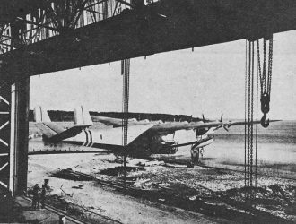
The Globemaster is the first airplane to carry its own cranes, hoists and cargo
elevator. Loading equipment consists of two traveling cranes, supported on overhead
rails in the fuselage roof, and a stationary hoist forward of the cargo loading
door on the left side of the cargo cabin. An elevator, supported at the corners
by cables, lifts cargo into the cabin rapidly. When not in use, the elevator is
secured in place by a releasable latch mechanism and becomes part of the cargo cabin
floor. The slide door hoist can lift 4,500 pounds, the cranes a total of 16,000
pounds when used together.
Remember, this is a cargo version. As such, it is important to handle cargo fast,
and in quantity. The Globemaster, therefore, with its self-loading equipment can
load, stow and haul ten R-3350 engines and cradles, or two T-9E1 tanks, two quarter-ton
trucks and two crew-and-ammunition carriers. It can carry other combinations as
well.
But let's look at the commercial version briefly. How do we plan to make this
airplane more comfortable for passengers? First, it should be remembered that larger
and later airplanes create more trouble from the noise standpoint. Power increases
faster than the art of soundproofing advances. The greatest problem is to keep the
noise down to that experienced in the DC-3. Cutting propeller tip noise by keeping
tip speeds well below the velocity of sound is one answer. Placing propellers sufficiently
far ahead of the passenger cabin so that wash-rooms or partitions will be between
props and passengers is another. Creation of "floating cabins" by separating walls
and bulkheads from main walls with rubber extrusions is yet another. Pressurizing
the cabin cuts the noise by about seven decibels.
The DC-6, which was delayed by war production and will not be flown until sometime
in 1946, is very like the DC-4. Innovations include an extra eighty inches in the
fuselage, R-2,800 Pratt and Whitneys instead of the R-2000s in the C-54 and also
a cruising speed of 300 miles an hour against 240. It will be completely pressurized,
with a cabin that can be either heated or cooled to an even temperature of seventy
degrees F. There is no change in wing span over the C-54, but a higher lift flap
will be employed. Three models will appear: the seventy-passenger day plane, the
fifty-two-passenger day plane and the twenty-six-passenger sleeper.
Passengers generally consider the DC-3 to be a comfortable airplane in which
to fly. But the successful airline operator knows he must compete with both air
and ground facilities to provide even greater comfort in order to hold and increase
his business. In the DC-6 all-sleeper deluxe, therefore, passengers will enjoy more
reliable heating and ventilation, better lighting, up-to-the-minute food service.
Due to its higher wing loading, 32.2 pounds, the DC-6 will ride more easily since
it will be less responsive to gusts.
These are generalities. They had to be worked out in minute details. E. Hamilton
Wright, chief of interior design for the company, sketched a dozen cabin interiors.
He built miniature cabins with miniature furniture. He painted them in various pleasing
combinations. As a result, should you ever fly in this airplane, you will enter
a door conveniently set just aft of the wing. From the foyer you may turn into either
the forward or aft cabin.
Once all passengers are aboard and the door is closed, the stewardess will commence
preparation of your next meal, working from two buffets, one on each side of the
door. From the rear buffet, she will take trays pre-loaded with fruits and load
them at the forward buffet with hot foods and liquids kept warm in thermos units.
You will relax in soft, luxurious cushion-rubber chairs. Later you may stroll
forward (if a gentleman) or rear (if a lady) to either lounge. In each will be found
a score of built-in accessories, as ash trays and electric connections in the men's
lounge. There will be a large sofa in the ladies' lounge. Indirect lighting will
illuminate each, while a lens shaving light will be provided for the necessary male
routine.
Long arm-rests, adjustable backs, removable and adjustable head- and foot-rests,
with full clearance for legs and luggage, characterize the seats. After darkness
falls, the stewardess will pull a few levers, and the seats will become berths.
Nor need you dawdle in the aisle aimlessly, for lowers will be made in thirty seconds,
uppers in ten!
The DC-6 and DC-7 serve the needs of long-range operations. The airlines have
other needs and to fit them we shall have the DC-8. This will be a low-wing, twin-engine
airplane which may well constitute as great an advance over the DC-3 as the Ford
tri-motor was over the Wright brothers' original biplane. The Sky bus will cruise
at 270 m.p.h. at 10,000 feet. It will perform beautifully on a single engine at
more than 12,000 feet and at the same time its landing speed is extremely low. Another
interesting innovation from an operations standpoint is that both take-off and landing
weights are the same, a gross of 39,500 pounds.
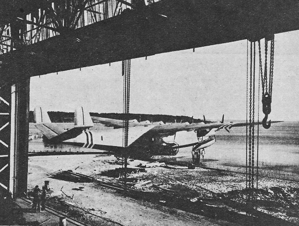
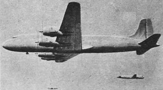
Latecoere De Marmier
The giant French flying boat, Latecoere 631, surnamed De Marmier after a French
war hero, is here shown shortly before its trial hop from Bordeaux to Buenos Aires.
Kept from Nazis by the French, she holds 100 passengers, ranges 6,000 miles.
We built for comfort in other airplanes, but in this one we tried to attain considerably
greater speed than we had in the DC-3. In fact, the DC-8, which will have motor
less wings and be driven by twin counter-rotating propellers, astern of the fuselage,
will be fifty percent faster than the DC-3, carry twice the number of passengers
and reduce direct costs per passenger-mile to half that of the plane which for twelve
years has been standard equipment on ninety-five per cent of the world's airlines
and supplied most of the Army's transport.
The DC-8, which will not appear for some months yet, represents a radical departure
from tradition. It will be driven exactly as an ocean liner is driven. It is in
the application to aircraft of this basically new principle of "center-line thrust"
that we believe the DC-8 represents outstanding improvements over conventional types
in speed, safety, climb and efficiency.
But it does not omit passenger comforts. A cabin innovation of great significance
is a movable partition that converts the plane at short notice from a combination
cargo-passenger to an all-passenger plane. By this means, the operator can be assured
of a 100 percent load on all flights where passengers and/or cargo are available.
The two engines, located in the fuselage below the forward compartment floor, are
connected with the propellers by drive shafts and a gear box similar to those of
an automobile. Allison engines were chosen because they were installed in military
experimental prototypes which have been test-flying for more than a year. This power-propeller
installation means a further reduction of noise within the cabin. Improved safety
is derived, too, since there is no offset thrust in case of engine failure, there
is an overall drag coefficient twenty percent less than in equivalent conventional
planes and better lift distribution resulting from the higher effective wing span.
Other details cannot be revealed to the public at this time.
There are some significant trends to be traced in the history of the DC family.
High strength materials have made an average of a fourth to a third increase in
strength. Later models use the new 75S aluminum alloy in all basic structures. All
models up to theDC-7 have three-spar wings. However, the DC-7 incorprates two-spar
wings, a change which increased fuel capacity by fifty percent, and thus increased
the range by the same proportion. All models through the DC-3 used brazier head
rivet construction. The DC-4, 6 and 7 have flush rivet construction, effecting lower
drag. Other improvements in later models result in lower drag and better cooling
in the nacelles. One of the biggest improvements is the complete sealing off of
the engine from the rest of the airplane structure, a change first appearing on
the original DC-4, The Skymaster.
It's a long road -fro m the DC-1 of twelve years ago to the Globemaster and the
Skybus, but it is one road. We have really been writing variations on a theme. For
though the granddaddy of them all weighed in at only 17,500 pounds (gross weight)
and the mightiest of her progeny, the Globemaster, weighs 155,000 pounds; though
the wing-load has increased three-and-a-half times, the first of the line was so
well engineered that very few fundamental changes had to be made. Each late model
grew out of the one that preceded it.
An airplane isn't really built; it is a process of evolution.
Posted July 16, 2022
|