|
Buhl Aircraft
Company, founded in 1925 in Detroit, Michigan, really had just two
successful airplane designs - the CA−6 Airsedan and the LA−1 Bull Pup. The
Buhl A−1 Autogyro
was a novelty aircraft that never gained popularity. It came out in 1931, a year
before the company went out of business. This 1/2A size Bull Pup construction by
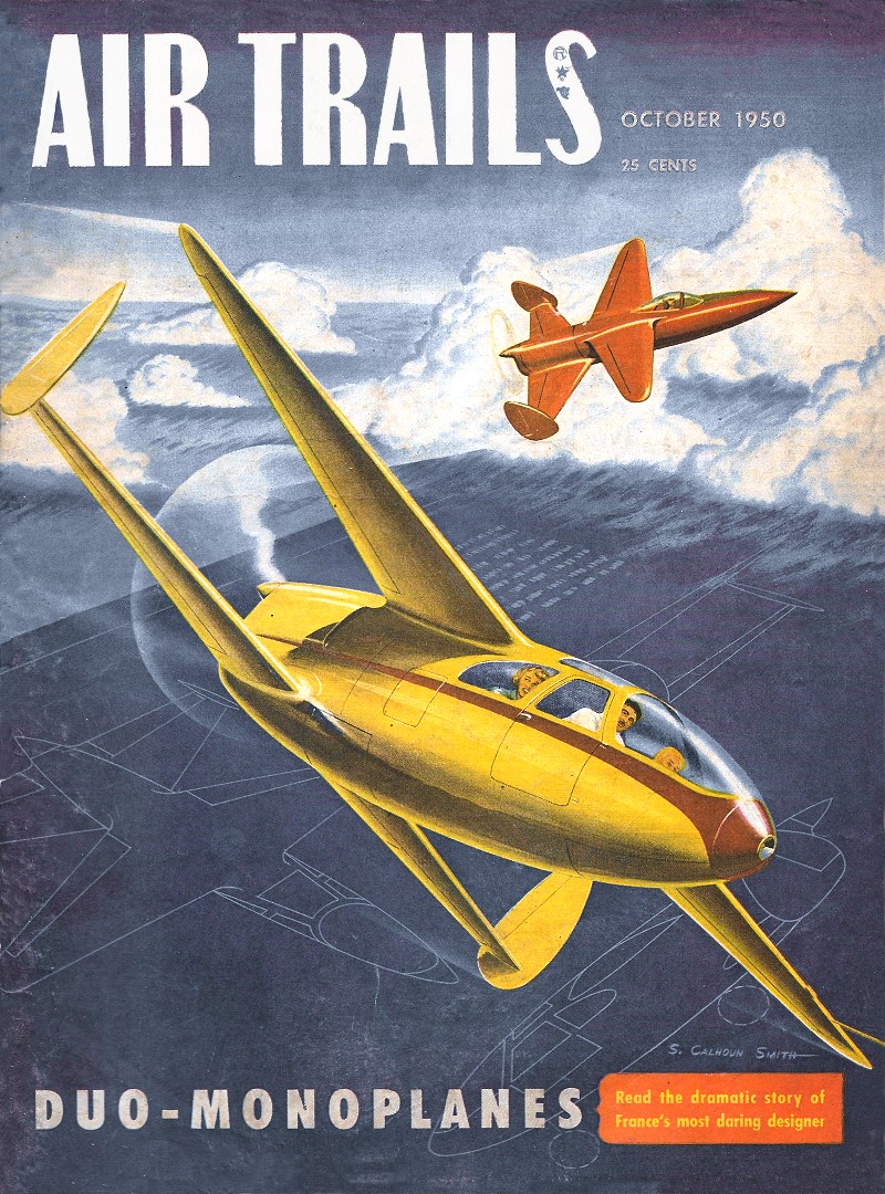
Charles Hollinger article and plans appeared in a 1950 issue of Air Trails
magazine. The Bull Pup began life as a rubber powered model, and Mr. Hollinger
adapted it for powered free flight at a request from Air Trails
editors. Its 35" wingspan is a convenient size and makes for an economical
building project, even more so with today's balsa prices. A conversion to
electric power with three-channel R/C would be easily accomplished.
Buhl Bull Pup
 By Charles Hollinger By Charles Hollinger
A gem for the free flight scale enthusiast - and we see those scale stunt men
grabbing this one but quick
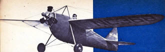
Twenty years ago the Buhl Aircraft Co. announced their new light plane the "Bull
Pup." Several versions were produced with wingspreads ranging from 27 to 36 feet.
This resulted in either a high top speed plus high landing speed with the small
wing, or a slight sacrifice in speed for slower landings and higher ceiling with
the 36-foot wing installed.
 The "Pup" seated one occupant, had a three-cylinder
Szekely in the nose and a top speed of 90 mph, which was doing right well for only
45 horses. The fuselage was of all-metal monocoque construction. It was one of the
first light planes to use this advanced feature. The "Pup" seated one occupant, had a three-cylinder
Szekely in the nose and a top speed of 90 mph, which was doing right well for only
45 horses. The fuselage was of all-metal monocoque construction. It was one of the
first light planes to use this advanced feature.
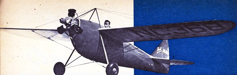
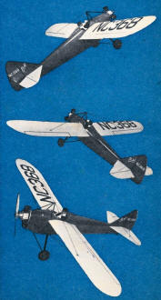
Our model happened to be one of those last-minute affairs built for entry in
last year's Nationals. In spite of the rush job it received the highest points for
workmanship and scale of all the rubber-power flying scale entries, dropping to
third, however, when the flight points were added. This was with two official flights
since the rubber motor broke on the third wind-up, necessitating repairs to the
fuselage.
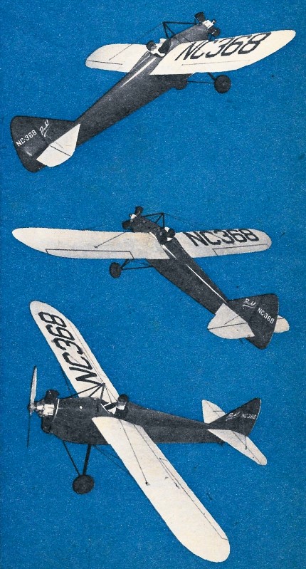
AT's editors saw the Pup at the Nats and thought it would make a good Half-A
flying scale. The changeover from rubber to gas power was very simple and has resulted
in not only an attractive display scale model but one that is an exceptionally stable
and a realistic flyer as well.
The real cylinder fits into the nose so perfectly that it takes at least a second
look to discover "which triplet has the piston." Any of the small motors from .035
to .049 may be used for free flight. If you would like to convert the Bull Pup into
a scale control liner, the best performance would be with .074 to .099 motors.
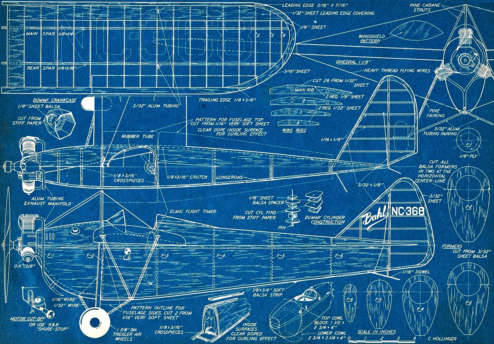
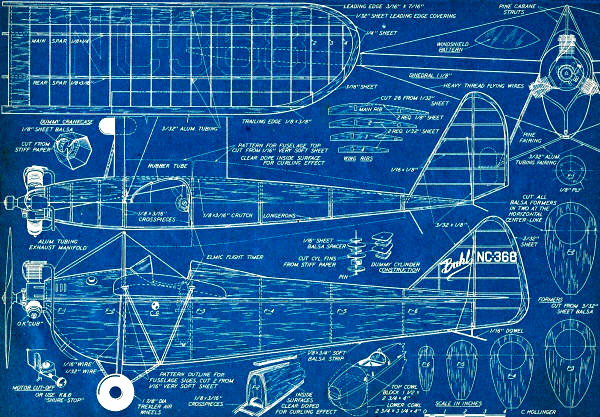
The fuselage may be started by laying out two strips of 1/8" x 3/16" over the
top view of the plans. Use pins to hold them in place along the fuselage outline.
This will furnish the crutch onto which the fuselage formers will be attached. Cut
the crosspieces of the same stock and cement to the longerons. Formers 2, 3, 4,
5 and 6 are now cut out of soft 3/32" sheet and then cut horizontally at the centerline
as the bottom of the fuselage is assembled and sheeted while the crutch is still
pinned to the plan.
With the lower sections of the formers cemented in place you are now ready to
sheet the bottom section. Be sure to get the very softest 1/16" sheet you can find,
for it will curl more easily. Cut these sheets to the pattern shown along the lower
edge of the side view and brush on three coats of clear dope extended to about the
position of former 5 on the inner sides only.
As the dope dries it will begin curling the sides, so now is the time to cement
them to the fuselage crutch and to former 6. When this is dry cement the sheets
in contact with formers 3, 4 and 5, using plenty of pins to help hold them to the
formers. If the sides aren't curling enough, dampen a rag and rub over the areas
where more curve is desired. Before cementing the front edge down to former 2. Force
it down by hand, and if it tends to buckle slightly cut a slit 1/16" wide at the
front tapering to nothing at former 3, then cement to former 2. Take a scrap piece
of 1/8" x 3/4" sheet and lay along the bottom. Lift this completed structure off
the plan and glue the top formers in place.
The top of the fuselage from former 3 back to 6 is covered in one piece. Dope
the inside as you did on the bottom but apply several extra coats toward the tail
as it will have to curl more sharply. The covering from former 2 to 3 is one piece.
but don't cut out for the cockpit until the fuselage is ready for covering. A small
block is used to fill in the section on top from former 6 to the end.
Cut the two soft balsa cowl blocks to approximate shape, then lightly cement
onto the nose. Carve and sand to conform to the fuselage, then cut loose and hollow,
re-cementing solidly to the fuselage. Two sections cut from 1/4" hard balsa 1/2"
long are cemented onto the front of former 2 for the upper part of the main landing
gear wire to enter. Former 1 may be cut out now, but do not cement it to the fuselage
yet. Carve the headrest and cement to fuse. The finish of the fuselage is greatly
improved and is much stronger if you cover it with tissue.
The tail surfaces are of the usual construction and are covered with light tissue,
not Silkspan. Spray lightly with water to tighten.
For the wing, cut out the ribs from 1/32" sheet, or if you're allergic to cutting
out so many ribs the number may be reduced to one-half, but in this case use 1/16"
sheet instead. Two of the ribs next to the fuselage are cut from 1/8" sheet, following
the dotted line on top of the rib for the outline in place of the solid line. The
two ribs next to these are also trimmed along the top.
For assembly, slip the ribs over the spars to their approximate spacing, then
lay on the wing plan and pin the spars in alignment with the drawings. Now true
up all the ribs and cement to the spars. The trailing and leading edges may now
be cemented to the ribs. Cut the wing tips from the required thicknesses of scrap
balsa. The 1/32" sheet leading edge covering is cut to the required width, then
cemented along the leading edge.
When this is dry, cement the rear edge of the sheet down to the ribs, using pins
to hold in place. Don't forget the 1/32" sheet covering over the first two ribs
at the wing root. Now the two short lengths of 3/32" aluminum tubing may be cemented
alongside the rib as shown on the plan. This will give the right wing panel. However,
it will be necessary to turn the plan over in order to get the left panel. A small
amount of oil or Vaseline applied to the wing plan will make the paper translucent.
Repeat construction. After carefully sanding the two panels, cover with tissue and
spray with water.
Now we finish the fuselage. tail surfaces and wing panels. Brush two coats of
a mixture composed of equal parts of clear dope and clear lacquer over the fuselage
and wing, but only one coat on the tail surfaces, If at all possible spray the remaining
finishes. Now apply two coats of wood filler or automotive primer to the fuselage,
sanding between each coat. Spray three coats of red to the fuselage and rudder.
The wing and tail will require three coats of cream.
The main landing gear strut is formed from 1/16" dia. wire, using the front view
on the plan for the exact shape. Run the wire one-half inch into the fuselage. The
supporting struts are bent from 1/32" dia. wire with sections of slightly flattened
3/32" dia. aluminum tubing slipped over.
Before mounting the wing panels it will be necessary to cut slots in the fuselage
for insertion of the wing spars and leading and trailing edges. Slip the panels
in place and raise each tip to its required dihedral. The flying wires are composed
of heavy thread and are threaded through the aluminum tubing inserts in the wing
and through a hole at the top of the cabane struts. Pull all wires tight and cement
not only the thread, but also the leading and trailing edges to the fuselage.
Mount the gas tank inside the nose as far forward as possible. Bolt the motor
to former 1 and securely cement onto the nose. The dummy crankcase and dummy cylinders
will greatly increase the appearance of your model while requiring only a slight
amount of extra work. The exhaust manifold is probably the most difficult part of
the model. One of the best ways to make a sharp bend with aluminum tubing is first
to fill the inside with solder, bend to the desired-arc, and then melt the solder
out. Be sure to get the softest grade of aluminum tubing for this.
If you will be flying your model within small areas it would be well worth putting
in a Maeco flight timer as it weighs practically nothing and gives you complete
control of the ship's flying radius.
Before going out for the first flights check your model for its balance point
and compare with the c.g. location as shown on the plans. If it is close you are
ready for your trial flights; if not, it will be necessary to add a slight amount
of weight to either the nose or the tail until it balances correctly.
As with ail free-flight models it is best to hand-glide the model, adjusting
for a straightaway or large circle without any signs of a stall. The model is now
ready for its power flights. and you will find it to be an exceptionally easy ship
to adjust and one that can take more than its share of the usual knocks.
Buhl Pup Plans
Notice:
The AMA Plans Service offers a
full-size version of many of the plans show here at a very reasonable cost. They
will scale the plans any size for you. It is always best to buy printed plans because
my scanner versions often have distortions that can cause parts to fit poorly. Purchasing
plans also help to support the operation of the
Academy of Model Aeronautics - the #1
advocate for model aviation throughout the world. If the AMA no longer has this
plan on file, I will be glad to send you my higher resolution version.
Try my Scale Calculator for
Model Airplane Plans.
Posted December 26, 2020
|