|
This article for the
rubber-powered free flight Penni Helicopter, by John Burkam and Gene Rock,
was scanned from my purchased copy of the January 1970 American
Aircraft Modeler magazine. The Penni Helicopter is fairly unique in that it
has a functional tail rotor to counter the main rotor torque rather than
just a big flat vertical surface. It also features a flybar on the rotor
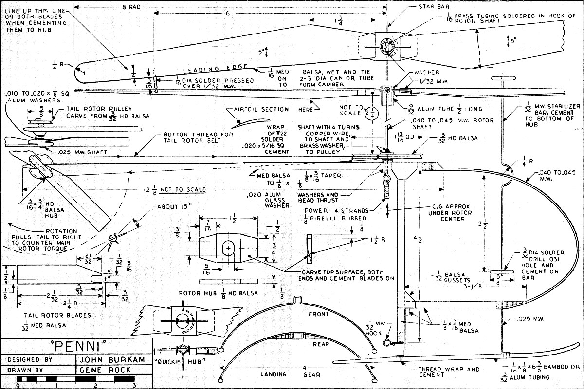
head to help stabilize flight. Main rotor span is 16 inches. Because the
plans spanned two pages, I had to adjust the size and alignment a bit to get
halves to line up properly. The AMA Plans Service does not carry the Penni
Helicopter, so if you need a larger version, e-mail me and I will send you a
4.5 x 3.0 kpixel version. You should be able to scale up the image below,
though (click on image for larger version).
See John Burkam's article "Designing
RC Helicopters" in the March 1971 issue of American Aircraft Modeler.
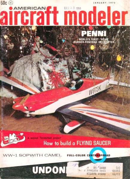
Penni Helicopter
 World's first, real, rubber-powered copter
is simple but a scientifically developed free-flight demonstrating all principles
of rotor-wing operation. Build it from scrap!
John Burkham
 Many
men came to me after I flew Penni in the auditorium at the DC/RC Symposium last
May and quoted their sons as saying, "Daddy, make me one of those, please!" It is
rather cute flying around like a real chopper and it's fairly easy to make - especially
if you use the "quickie" hubs instead of the universal hub. Most of you can build
it from the plans only, referring to the text in case it doesn't fly right away. Many
men came to me after I flew Penni in the auditorium at the DC/RC Symposium last
May and quoted their sons as saying, "Daddy, make me one of those, please!" It is
rather cute flying around like a real chopper and it's fairly easy to make - especially
if you use the "quickie" hubs instead of the universal hub. Most of you can build
it from the plans only, referring to the text in case it doesn't fly right away.
This little model was designed during my lunch periods at work and mostly built
there, too. She was made specifically as a stability or instability demonstrator
for the DC/RC Symposium in May 1969. Big enough to have decent performance, but
not big enough to be damaged when colliding with tables, lamps, etc.
If you build the universal hub you can press in balsa plugs or wedges to prevent
tilting of the aluminum tub with respect to the shaft and/or the hub: You can demonstrate
the stability of the completely free universal hub with stabilizer bar and of the
feathering-only hub with stabilizer bar. (Feathering is pitch changing of both
blades, one up, one down, about the hinge axis which is nearly parallel to the blades.)
You can also demonstrate instability of a completely rigid rotor; that is, no feathering
or teetering, and of a teetering-only rotor.
If you don't want to experiment you can just build the "quickie" hub shown and
have a model that flies just as well as or better than the universal hub. You'll
notice that on the quickie hub the blades can feather easily by twisting the feathering
pin in the diamond eye, but when the rubber is wound up and driving the rotor, the
force of the eye on the feathering pin creates friction to resist any up and down
sliding of the pin in the eye, as would be caused by flapping or teetering motion
of the blades. This friction damping of flapping motion prevents the fuselage from
swinging to and fro like the one with the universal joint.
Fuselage: You can start building any part, but I like to start
with the fuselage (sticks) and add the landing gear so it can stand up by itself.
You can add parts to that and not have them lying around loose, or lost.
Cut the ⅛ x 3/16" pieces to length and shape the ends as shown on the drawing,
taper the tail boom, and sand off rough edges. Mark on the balsa where they come
together, then cement them together at right angles to each other. (I recommend
Titebond for wood-to-wood joints and Duco cement for metal-to-wood except where
solder is called for. Epoxy also is good but is more trouble.) Glue on the 1/32
sheet balsa gussets.
Form the .045 wire nose piece, force the ends into the balsa sticks, wrap with
thread, and cover the joints with Duco cement. Bend the landing gear struts from
.025 music wire (.031 is ok if you can't get .025). The landing skids can be made
of bamboo or 3/32 aluminum tubing, or ⅛ sq. hard balsa.
If you get a 12" piece of aluminum tubing, r cut it into two 6" pieces and make
the skids a little shorter on each end than shown on the drawing. Bind the rear
strut to a curved piece of 'Is hard balsa and cement it to the fuselage after cutting
a small notch for the wire to fit up into. Press the front strut down onto the fuselage,
bind with thread, and cement. After the struts dry in an approximately straight
position you can tie on the skids. Here is where you find out why the front strut
ends bend forward and the rear strut ends bend backward.
Heart of a copter is rotor-head assembly. The more complicated
universal hub is shown.
A pin, left in photo, goes through the hub and little tube on
the rotor shaft below.
Note how stabilizer bar bends around hub. It controls individual
blade angle of attack.

Tail rotor spins several times faster than main rotor. It has
fixed pitch only.
Put marks on the skids where the struts are to be fastened. Hold a skid in about
the right position and wrap a rubber-band tightly around where one strut touches
the skid. Now wrap thread around the other strut and skid. Remove the rubber band
and wrap the first strut and skid. Do the other skid same way, line up both skids,
and cement with Duco. Now she sits on her feet.
Hook, Rotor Shaft, Pulleys: Bend a small hook as shown and glue
it on the bottom of the motor-stick. Get thin aluminum (.010 to .020) or find an
aluminum beer can. Even a thin tin can will do. This is for washers. Cut two washers
rectangularly, ⅛ x ¼, and drill a hole in the center of each just a hair bigger
than the size wire used for a rotor shaft.
If you don't have drills that size make one or two out of music wire. File the
end flat like a tiny screwdriver then bevel the end at an angle on each side, coming
to a point in the center so it looks like the end of a regular drill except for
no twisted flutes. If you're drilling tin-can steel, a needle sharpened like a drill
holds up better. And" if your hand-drill or electric drill won't take that small
size, solder a piece of 1/16 brass tubing, or rolled-up tinplate, on the back end
of your homemade drill. This drill, being so small, should be long enough only to
stick out of the chuck ¼" or less. You could also use an X-acto pin vise and twirl
it between your fingers.
Drill a hole down through the fuselage stick for the rotor shaft. If it leans
to the left a little, say three or four degrees, OK. That will tilt the rotor to
the left and offset the thrust to' the right of the tail rotor. This is not really
important. Now stick a piece of rotor shaft wire through the hole and glue on the
bearing plate washers just made. Pull that wire out before it gets stuck in permanently,
cut off a piece 3112" long, and bend either a diamond-shaped eye in the end for
the "quickie" type hub, or a round eye to fit over the 1/16 brass tubing of the
universal hub.
Cut a 5/16 sq. piece of thin brass or tin plate. Punch or drill a hole in the
center of the brass, slip it up on the rotor shaft to a point 2¼" below the center
of the eye. Clamp the bottom half in a vise so that the square washer is held at
the right place and perpendicular to the shaft. Using soldering paste, solder it
securely there, because this washer takes the full tension of the rubber, and full
torque while you're holding it by the pulley and feeding the tail rotor belt onto
the tail rotor pulleys. Clean off all traces of soldering paste to prevent rust.
Draw circles on 3/32 hard balsa the size of the two pulleys. Cut out these circles
with sharp knife or razor blade and sand them to smooth circles. Drill a hole in
the exact center of each, the size of the wire that goes through it. Take out the
drill, slip the pulley blank on it and twirl it to make sure it isn't eccentric.
It must be in the center!
To make the groove around the edge of each pulley, start by cutting a small 1/32-wide
V-groove around the center of the pulley's edge. Be careful not to cut too deeply.
Next go around the edge again starting from a point about 1/64" from the edge and
cutting toward the center. When you get an even 60-degree V-groove all around the
edge, fold a piece of fine sandpaper and sand the groove with the folded edge. Dope
and sand the groove a couple of times, so that there is a smooth, hard groove that
the thread won't climb out of even when winding the rotor by hand.
Slip the big pulley on the bottom end of the rotor shaft and cement it to the
5/16 sq. washer. Cement another washer on the bottom of the pulley. Before the cement
dries, twirl the shaft in your fingers and, if necessary, force the pulley perpendicular
to the shaft. Cut out the three balsa pieces for the tail rotor. Slip on another
tiny washer, or a glass bead, add a little Vaseline or Lubriplate, and slip the
shaft into the fuselage main bearing hole.
To bend the hook on the wire without wrecking the fuselage, hold the wire in
long-nose pliers, then bend the wire around those pliers with another pair of pliers.
Start with the outermost bend and work back to the middle. You will have to guess
how long it should be before bending. This method avoids putting any force on the
balsa wood.
Tail Rotor: Finish the tail rotor before you lose the pieces. Drill a hole in
the 3/16 round piece for the tail-rotor shaft. Carve or sand a slight lifting airfoil
shape into the tail rotor blades and glue them onto the 3/16 round hub piece at
about 20 degrees to the plane of rotation. This is a left-hand prop, because it
is pulling the tail to the right when the bottom end is going aft, (rotation as
shown on the drawing). Again, stick a piece of straight wire in the tail rotor hub
and twirl it between your fingers slowly, to see if the blade angles are equal and
the the blades track or run true without a wobble. Make adjustments while the glue
is drying, then add a little more glue to make sure.
Glue a little block of ⅛ sq. balsa to the right side of the tail boom where the
tail rotor shaft is to go. Drill through for the tail rotor shaft and glue a washer
on each side for bearings as you did for the main rotor shaft. After the glue is
dry, take a piece of music wire the same size as the tail rotor shaft and clean
out the hole so the tail rotor turns easily.
Your own friendly copter is ready-to-sly. Paper used for drawing
is functional.
Now cut a piece of music wire for the tail rotor shaft, 1" long, and bend ⅛"
of the end at a right angle. Push it through the tail rotor hub, sinking the bent
end partly into the hub. Glue that end and also glue a washer on the other side.
Assemble the tail rotor on to the tail boom; stick the shaft through the hole, put
on a glass bead or very small washer, lubricate, add a ⅛ sq. washer, then the tail
rotor pulley.
Enough wire should be sticking thru to bend ⅛" of it over by the two-pliers method
without wrecking the pulley. Then slide the pulley out against the bent-over end,
cement the wire on both sides of the pulley and slide the ⅛ sq. washer against the
fresh cement on the pulley. Blow on the tail rotor to make sure it spins freely,
and that the tail rotor pulley runs true. Balance the tail rotor by adding a little
Titebond cement to the lighter blade tip.
Main Rotor: Cut out the blade blanks, soak them in water and tape them to a metal,
cardboard or glass cylinder 2 to 3" in diameter. Leading edges should be parallel
to the axis of the cylinder. Lay a piece of cardboard over the blades and wrap tightly
with rubber or string. The cardboard may not let the balsa dry as fast, but it prevents
the string from creasing the balsa.
Layout the hub, cut to shape, carve the top sides of the ends to fit the underside
of the blades, and drill out the oval center hole with sharpened end of 5/16 tubing.
Carve and sand the blades to a nice undercambered airfoil, using the can or tube
they were formed on as an aid in holding them. Cement the blades to the hub, using
a light line ¼" back of the leading edge to sight across, to make sure the blades
are directly opposite each other. Balance the blades on a knife edge crosswise at
the center of the hub, either sanding on the heavy blade or adding a little Titebond
to the tip of the light blade.
Cut a ½" long piece of 9/32 aluminum tubing and drill two holes through it at
right angles to each other, and at right angles to the centerline of the tube. These
1/32 holes are 3/32 from the end of the tube. Cut and bend the two L-shaped feathering
pins from 1/32 music wire and force the short end down through the blade into the
hub, so that the long end projects about 1/16 into the oval hole in the hub. Note
that these pins are on the centerline of the hub but that the blade leading edges
are swept five degrees forward of the centerline of the hub. This is important,
especially if you want to lock out the flapping bearing and fly it as a "hinge less"
rotor.
Now lift off the feathering pins, slip a small washer over each one and replace
. them with the 9/32 aluminum tube in position. Cement the feathering pins to the
hub. Cut a piece of 1/16 brass tubing just short enough to fit crosswise in the
9/32 tubing. Solder the brass tubing in the eye of the rotor shaft, centered up
and perpendicular to the shaft.
Cut a piece of 1/32 music wire 5/16 long and assemble the rotor to the shaft.
If the feathering pins project too far into the center of the 9/32 tube and hit
the eye of the rotor shaft, file them off a little. Of course, there should not
be too much solder on the tube and eye. A small drop of cement on each end of the
5/16-long music wire, where it sticks through the aluminum tube, holds it in place.
Bend the stabilizer bar and cement it, less weights, to the bottom of the rotor
hub. Make the two weights of equal size from 3/32 resin-core solder or just use
Du-Bro Dura-collars with 1/16 bore. If you want to be neat put a bushing of 1/16
aluminum tubing in each collar so it fits the stabilizer bar better. Slip the weights
on the ends of the bar and see if it balances. Move one weight in toward the hub
a little if necessary. Cement or tighten in position.
One thing hasn't been mentioned yet- those leading edge tip weights made of 1/16
dia. solder. First, see if they are necessary. My own blades, made from 1/32 balsa,
were very flexible, would not track properly, and had to have the weights. Put on
your four strands of Pirelli rubber (never mind the tail rotor yet), wind up to
a single row of knots, and see if the rotor spins true, or if one blade rides higher
than the other. (I blacken one blade tip with magic marker so I can see which one
is high.)
Whichever blade is high, bend up the stabilizer bar which comes before that blade.
Also, if necessary, bend down the bar which comes before the low blade. If you can't
get them to track, or if they are very sensitive to a small amount of bending of
bar, then add the tip weights, being careful to keep the blades balanced span wise.
Last, tie the tail rotor belt (button thread) in position fairly tight. The tightness
is not necessary to keep it from slipping, but to keep it from climbing off the
pulleys while hand-winding. Use a square knot and cement it after you have it tight
enough. Work the cement in with your fingers and remove I any excess.
Lubricating the rubber with purchased lubricant (or a 50-50 mixture of glycerin
and tincture of green soap) gets more power out of the rubber and allows more turns
to be put in.
If you want to build the quickie hub, make one long feathering pin instead of
the two L-shaped pins. Put two washers in the center of this, push the bent-down
ends into the hub, and cement it there. Push' the washers out to where they touch
the balsa and cement them there, Now, the diamond-shaped eye at the top end of the
rotor shaft should just take up the space between the washers when it is assembled
and in driving position.
Flying: The CG of the model should come under the center of the rotor. When you
launch the model, let go of the rotor first, then a second later release the fuselage.
If you want it to rise straight up launch it level. If you want it to fly forward,
tilt it forward about 10 degrees. If the tail-rotor thrust is too great for the
torque of the main rotor (turns left while hovering) cut a little area off the tail
rotor blade tips. If it turns right while hovering, increase the tail rotor blade
angle, after making sure that the belt is not slipping.
The AMA Plans Service offers a full-size version of plans at a very reasonable
cost. They will scale the plans any size for you. Try out my
Scale Calculator
for Model Airplane Plans.
https://www.modelaircraft.org/plans.aspx

Penni Helicopter Plans <click for larger version>
Notice:
The AMA Plans Service offers a
full-size version of many of the plans show here at a very reasonable cost. They
will scale the plans any size for you. It is always best to buy printed plans because
my scanner versions often have distortions that can cause parts to fit poorly. Purchasing
plans also help to support the operation of the
Academy of Model Aeronautics - the #1
advocate for model aviation throughout the world. If the AMA no longer has this
plan on file, I will be glad to send you my higher resolution version.
Try my Scale Calculator for
Model Airplane Plans.
Posted June 28, 2021
(updated from original post on 11/13/2008)
|