|
The
Pilatus Porter, manufactured
in Switzerland, is now just a part of Pilatus' considerably expanded product line. Since
its original STOL flying machine, the company now makes business jets and military trainers.
Various iterations of the Porter are seen at scale model contests worldwide, and there
are multiple kits and ARF versions available for free flight, control line, and radio
control. What makes this particular Pilatus Porter noteworthy is its builder and pilot,
Mrs. Dolly Wischer, who appeared with it in an article in a 1963 edition of American
Modeler magazine. She researched the design, drew the plans, built the airplane,
and flew it with one of the earlier proportional radio control systems. Its 68" wingspan
and a wing loading of just under 22 oz/sq.ft. allowed a .19 engine to drag it around
the sky handily.
The AMA Plans Service
(somewhere around page 18) still sell plans for this
Pilatus Porter, as well as for 15 other versions! I told you it is a popular scale subject.
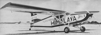
Dolly Wischer's "Yeti" Radio Controlled Pilatus Porter
|
Wisconsin housewife, mother of R/C Rudder Champ, designed, built and
operates this scale flyer, gives her own story and plans-yes, drew 'em herself!
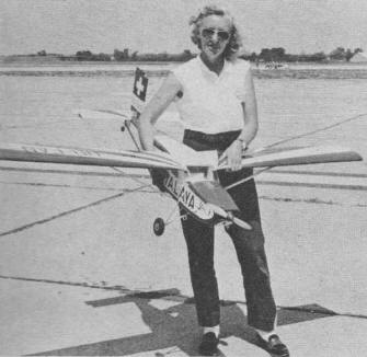
Mrs. Robert (Dolly) Wischer with her R/C Porter entry at last year's
National Meet, Glenview, Ill., Naval Air Station.
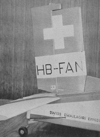
Tail unit of Pilatus Porter; shown are push rods for moving rudder
and tailwheel.
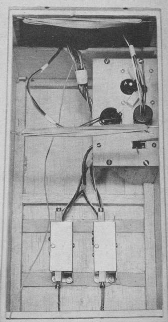
Interior (nose upwards): plywood panel holds switch, connecting plugs
and Hillcrest throttle servo. Annco servos at bottom.
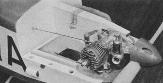
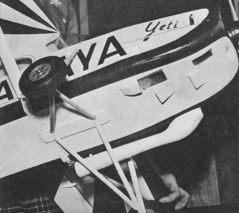
Engine mount details: Piano wire push rod emerges from aluminum tube;
sheet aluminum covering to protect balsa from castor oil was made from cookie sheet (the
woman's touch!).

Under-body view, aluminum liners for the exhaust and engine cooling
vents are visible.
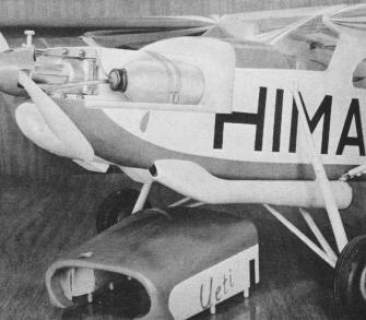
Porter model with cowl removed, note 2·oz "clunk" type fuel tank held
in place via rubber bands and hooks. Mrs. Wischer's faithful copy is based on geared,
super-charged standard Porter powered by Lycoming GSO-480. Cover drawing by Cal Smith
depicts the Turbo-Porter with Turbomeco-Astazou powerplant.
|
There is considerable variation in opinion of what constitutes a pretty airplane.
Some prefer sweeping curves and elliptical wing outlines, while others like straight
lines with a long, slender appearance. The Pilatus Porter is obviously neither of these;
its utilitarian shape is square to the extent that it seems to have been built in long
lengths which were then sawn off into shorter chunks. However, in spite of those functional
lines, her designers have come up with an airplane that has an appeal to any person who
feels an affinity for things that fly, and I suspect that I am one of these.
The model was inspired by the reading of the mountaineering book "The Ascent of Dhaulagiri,"
a narrative of the successful 1960 Swiss Expedition to climb the 26,795 foot mountain,
Dhaulagiri, in Nepal. At that time it was the highest unclimbed mountain in the world.
The Swiss used the airplane to supply the high camps in place of many Nepalese porters.
The Pilatus Porter made between twenty and thirty landings at altitudes from 15,000 to
19,000 feet-and holds the world record for a landing at 19,200 feet. All of these landings
were made with loads such as carrying 1,500 pounds of rice to a glacier at 15,000 feet.
For this type of work the Porter is equipped with a combination of skis and wheels, the
skis being hydraulically raised or lowered depending on the surface encountered. The
expedition plane was christened "Yeti", the Nepalese word for the elusive abominable
snowman.
The Porter is a product of the Pilatus Aircraft Works of Stans, Switzerland, who generously
supplied us volumes of necessary information and drawings. It is the most outstanding
of the STOL aircraft. Powered by a geared super-charged Lycoming six cylinder engine
of 340-hp, it can lift a useful load of 1,900 pounds with a ground run of 525 feet and
a landing run of only 330 feet. Cruising speed is 125-mph, top speed is 145, and it stalls
at 43. A later version employing the Turbomeca Astazaou turboprop powerplant (see Cal
Smith's cover painting) has even more spectacular performance.
A prominent feature is the exhaust augmenter tube which also carries off the air used
for cooling the engine. The wing trailing edge is almost evenly divided between flaps
and ailerons. The plane can carry seven passengers plus pilot, and is easily adaptable
to photo, cargo, and parachute work. The first Porter was purchased by Hermann Geiger,
the famous Swiss alpine pilot, for utility and rescue flights in Switzerland. "Yeti"
was the third plane built, and four others are operated by the International Red Cross
in Nepal. The first in the United States was purchased by Wein Alaska Airlines.
Our model was developed around six channel multi equipment. The ailerons and flaps,
although built separately and glued in place for realism, could easily be made operable
if eight or ten channels are available. Since a plane like the Porter is not considered
acrobatic, ailerons are not a requirement for realistic flight. The space inside the
model is so vast that any amount of electronic gear could easily be installed, but more
power than the Veco .19 would be needed. In order to simulate the all-metal construction
of the full size Porter, the model is entirely covered with sheet balsa. It is important
to choose only the lightest wood for this purpose in order to keep the weight down to
a reasonable five pounds or less.
The squareness of its outlines makes "Yeti" quite simple. Wing tip ribs and root ribs
are the same shape, which means that the right and left panels will be identical until
strut anchors and end ribs are cemented in place. The airfoil employed for the model
is an NACA 2414, quite different from the reflexed high lift airfoil of the prototype.
Aerodynamically this change was not absolutely necessary, but an undercambered airfoil
is more difficult to construct and it was considered a good idea to concur with usual
R/C practice. As it turned out the choice was a good one since the plane flew well, without
any adjustments, on its first flight. While the model has little dihedral this does not
affect its performance adversely since the center of gravity is low.
Every scale modeler has a problem with the horizontal stabilizer because it usually
has too small an area compared with modeling practice. In this case the decision was
made to conform with the scale area, as this helps in obtaining maximum scale points
in a contest. A bonus benefit derived from the small stab is that the plane takes off
well even though the main landing wheels are quite far ahead of the center of gravity.
The usual ground loop doesn't develop because the tail wheel stays on the ground until
a good speed is built up, and by that time the large fin and rudder take over to hold
the plane in a straight line take-off. Past experience had shown that an oversize stabilizer
will cause the tail to lift too early with a resultant ground loop. Once airborne the
Porter has all the stability of the full size plane, showing no bad handling characteristics.
(My husband calls it an old ladies' airplane.)
The fuselage conforms with present day R/C construction practice with minor variations.
A large hatch in the roof permits easy access to a cavernous interior, where the Annco
servos, mounted on the floor, appear lost. Batteries and receiver are wrapped in foam
and placed at the front. Fuselage sides have doublers extending from the cabin rear to
the firewall. Forward from this point the nose is solid balsa underneath, with a built-up
balsa cowl covering the engine and fuel tank. The unique landing gear extends from the
fuselage centerline and due to its length is quite springy. It has a very realistic soft
action in landing, and has saved the plane from damage on occasion. Spoked Veco wheels
closely simulate those used on the prototype Porter. Dummy shock struts are actually
telescoping birch dowels, and serve no purpose in load carrying.
Fastening the wings to the fuselage sides permits the windshield to be made in one
piece for greater scale fidelity, but this means that the wing halves must be keyed accurately
by tongues extending from the wing roots through alignment holes. Heavy rubber bands
then hold the wings snugly, but not too tightly, against the fuselage. On a hard landing
the rubber bands stretch, permitting the wings to swing downward and forward, pivoting
around the struts. This system works well in practice, but for inverted flight the bands
must be tight. Holes through the solid nose block for engine exhaust and ventilation
could be coated with polyester resin or, as in my "Yeti", lined with sheet aluminum to
prevent soaking of the wood with castor oil. In any case, the exhaust heat must not bear
directly on the balsa wood since this would constitute a fire hazard.
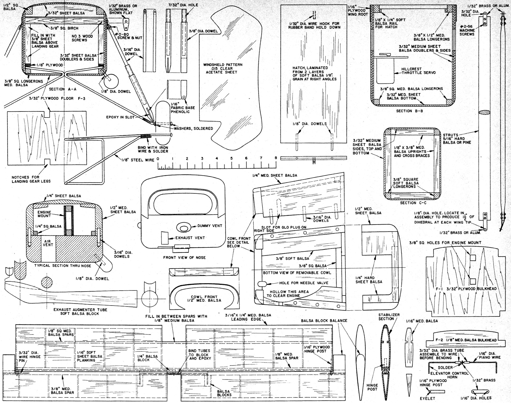
Construction. Fuselage sides are best made from 3/32" thick, 6" wide balsa sheets;
can also be spliced from 3" sheets. Score the sides on their inside surface with a razor
saw at the point where they bend inward at the cabin rear. Use cement liberally to reinforce
this score line after bending to the proper angle, using the fuselage top view as a template.
The 3/32" doublers are duplicates of the fuselage sides except that they end at the cabin
rear. Doublers are beveled at the back end to fit the bent fuselage sides closely. Use
contact cement to fasten sides to doublers making certain that there is a firm bond at
the point where the sides were bent. Now add the short doublers at the point where the
stabilizer will be attached. At this time cut-outs for the windows and windshield openings
should be made.
Cement all longerons and vertical braces to each side before joining the sides with
bulkhead F-1 and the cross braces thru the cabin section. Then add cross braces from
rear of cabin to tail. Bend the landing gear wires to shape. Note that each half is formed
from a single piece of wire. Cut plywood floor F-3 and insert landing gear into the notches
after which the ends of wire are bound with iron wire and soldered. Cement F-3 to fuselage
bottom and add 1/8" x 3/8" plywood pieces above landing gear followed by 3/8" sheet balsa
back-up blocks. Rigidity here is a necessity as a hard landing would force the landing
gear levers upward.
Complete fuselage structure by adding sheet balsa top and bottom, bulkhead F-2. and
cowl top. Tailpost is 1/2" square balsa sanded to cylindrical shape.
Fuselage nose blocks are best built in layers in order to obtain the two openings
for exhaust and air vents. Use white glue to fasten the block to bulkhead F-l and then
sand to shape. Also use white glue to assemble the engine mount to the nose block and
bulkhead. Note that three cross braces at the landing gear are made from 3/8" square
birch or maple. A 3/32" plywood gusset at the tail is used for fastening tail wheel bracket.
Just forward of this gusset is an opening for access to elevator push rod.
Wings are identical, left and right, except for the plywood end ribs and location
of strut anchors. Ribs are assembled to spars directly over the plan, then leading and
trailing edges are added. Cement strut anchors, with blind nuts attached, into the notched
ribs, then cover lower wing surface with 1/16" sheet balsa making certain to leave a
hole for the wing strut screw into the blind nut. Cement plywood keys with piano wire
hooks to root end of each wing before adding the top 1/16" sheet balsa planking. A 1/16"
plywood tip rib is added next. The 3/32" plywood root rib must have holes to slip over
the keys. Make two more ribs identical with these root ribs from 1/16" plywood and cement
them to the fuselage sides in exact position shown on plan to obtain 1 1/2 degrees of
incidence, making certain that both wings will have identical incidence.
The
separate ailerons and flaps are made in a long strip which is cemented in position in
final assembly after finishing. Although sheet balsa planking on the wing adds weight
it also adds realism and strength permitting a lighter interior.
Tail surfaces are built up similar to the wing and covered with soft 1/16" sheet balsa.
The hinge is of the concealed type for realism but could be a thread hinge, the same
as used on most R/C models for much less effort in building. When hinging elevator to
stabilizer care must be taken to be sure that no cement creeps into the 3/32" brass tube
to bind.
The entire model should be given 3 coats of clear dope and then covered with silk.
To prevent warping, the hatch requires silk on both sides. (Careful, I had to make three.)
Apply 5 coats of clear dope sanding lightly between coats and follow with 2 or 3 coats
of sanding sealer, again sanding between coats for a blemish-free surface. Two coats
of color should then be sufficient to cover the silk but many more may be added if a
superior built-up finish is desired, keeping in mind that additional coats add weight.
The flying characteristics of a model invariably suffer when the finish weight is
too high. The March-April, 1963 issue of American Modeler contains an excellent summary
of finishing techniques by Paul Plecan, an expert in the art.
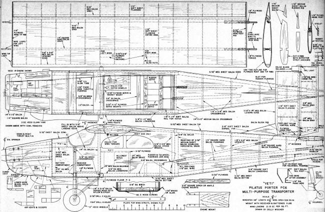
Pilatus Porter Plans (sheet 1)
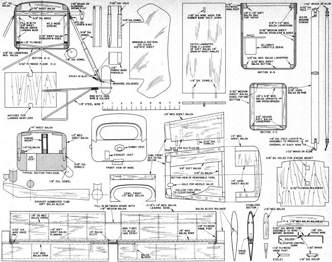
Pilatus Porter Plans (sheet 2)
Notice:
The AMA Plans Service offers a
full-size version of many of the plans show here at a very reasonable cost. They
will scale the plans any size for you. It is always best to buy printed plans because
my scanner versions often have distortions that can cause parts to fit poorly. Purchasing
plans also help to support the operation of the
Academy of Model Aeronautics - the #1
advocate for model aviation throughout the world. If the AMA no longer has this
plan on file, I will be glad to send you my higher resolution version.
Try my Scale Calculator for
Model Airplane Plans.
Posted April 11, 2015
|