|
Website visitor Steve G. wrote
asking that I post the article for the Viper R/C pattern ship that appeared in the January
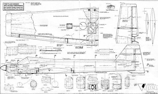
1973 edition of American Aircraft Modeler. The Viper won the "Best Original Design" award
and the "Most Outstanding Finish" award at the 1972 Toledo show. Data obtained during
research into a scale P-51 Mustang model contributed heavily to the wing and fuselage
design. At least four versions of the Viper were built by designer Dario Brisighella,
but the first, which won the Toledo trophy, had not yet left the ground at the time of
the article's publication. Viper is a full-house ship with a laminar flow foam wing,
balsa fuselage, retractable landing gear, and uses a Webra .61 Blackhead.
Viper
By Dario Brisighella, Sr.
Photos by Jonn Kozy
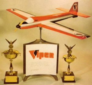
Viper won the "Best Original Design" award and the "Most Outstanding Finish" award at
the 1972 Toledo show.
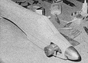
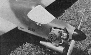 Neat and uncomplicated engine installation.
Webra rests on Kraft-Hayes plastic mount.
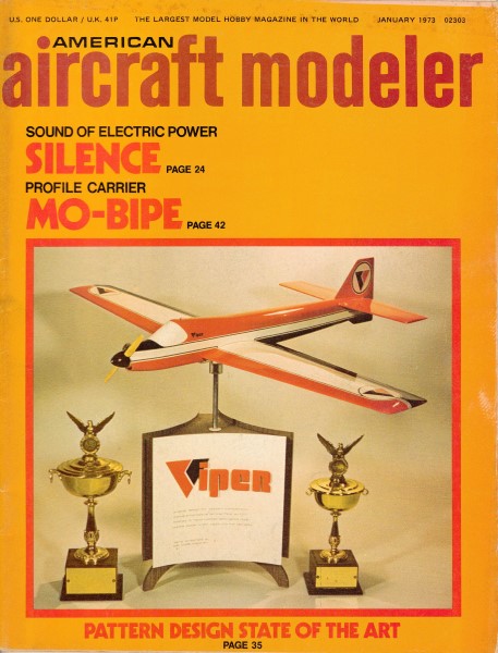
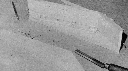
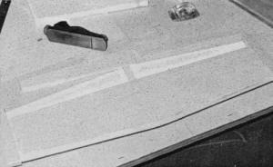
 Sheeted wing is ready for aileron and wing
facing, then hinging. This unusual airfoil required precision work.
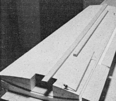
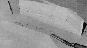
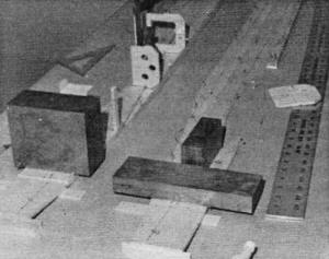 Rather than bend fuselage sides to fit bulkheads
under tension, sides are water and ammonia soaked and laminated for doublers and bent
on this jig. When dry, bend stays in without tension.
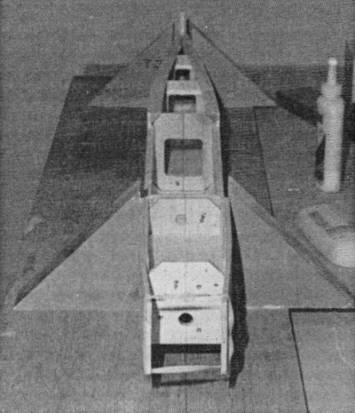
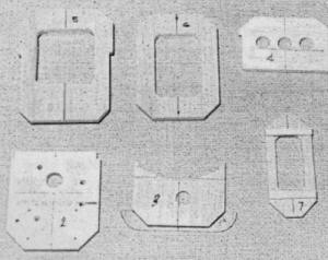 Very important to accurate modeling is use
of centerlines throughout. Text describes in detail.
 Thick airfoiled stab is balsa sheeting over
foam. Note that like ailerons, elevators are foam cored. This guarantees airfoil continuity.
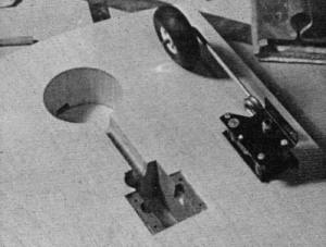 Pro-Line retract system is flown in one plane
and shown being installed here. Violett landing gears are also considered excellent.
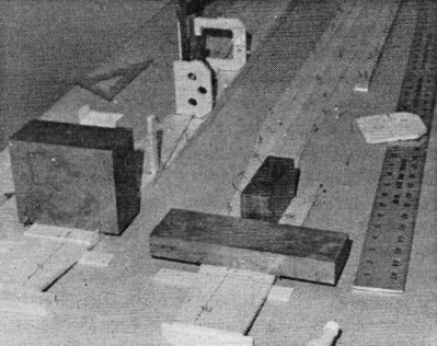
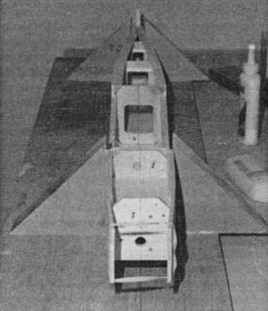 This shows proper lineup of the centerlines
and accurate fuselage side alignment with heavy triangles.
 What looks like a canopy is built up of balsa
blocks and triangles. Space inside will house battery packs.
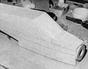 Before carving and sanding, fuselages sure
look ugly!
 A Viper takes on smooth curves. Fit the engine
to aid in shaping the nose.
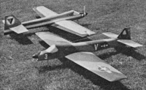 Vipers 1 and 3 differ in that the latter
model has less dihedral. Several have been made by very different builders; all perform
the same.
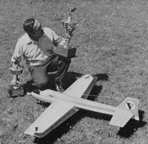 Author with Toledo winnings. Dario still
has not flown the original plane-it is too pretty! The others fly all the time when Dario
is not making helicopters.
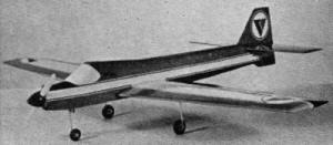 At rest on the gear, Viper has that look
of ready action. Note the moveable sub·fin. This is most helpful in wingovers |
The 1972 Toledo design and finish winner is a state-of-the-art pattern ship. Fast,
predictable, and smooth even in gusty winds. It is a model for the expert builder and
flier.
The word "intention," according to Webster's "often applies to little more than having
an idea in mind, or the will to act or do a certain thing." With this in mind, it would
seem that most modelers are inherently blessed with all manner of "good intentions/ideas."
In most cases, the only catalyst required to convert these intentions into reality, is
simply ample free time applied towards the varied types and numbers of model subjects
in mind for the future.
More often than not, we do complete some of our model-intentions. Some require the
passing of more time than others before completion. Then there are those which are just
passed over due to the advancements in the State-of-Art, or forgotten over the years.
I have dropped a few intentions along the way, as most of us have. On the other hand,
I have managed to complete some which date back a few years. Recently, for example, I
completed an intention of twelve years-that of restoring a full-size aircraft. Today
I am the very proud owner of a classic 1947 Stinson-Voyager, N-12-DB (Best Stinson Classic,
1971 EAA Convention). The original intention was easy to come by; the time for actual
restoration was "sumpin' else." The model presented here, though a new design, is really
the completion of another intention that dates back to 1969.
Ostensibly, Viper began as only an intention while completing the research covering
the North American P-51 Mustang for an ultra-scale model (another good intention). As
so often one project is shelved in lieu of another, so went the Mustang. My scale deHavilland
Hornet took its place, as did the Stinson restoration project. The Mustang remains shelved,
but that intention is the prime contributor and factor of this design.
Obtaining the airfoils and sections employed on the Mustang was a feat in itself.
Once accomplished though, these laminar flow designs really "turned me on." I became
intrigued by the rather unusual curves and reflexes of these high-speed sections. Thus
Viper-intention began. Someday I would experiment with these sections on a non-scale
design, or at least before completing the Mustang.
There were many long discussions about this project with other modelers. Seldom, if
ever, were there any encouragements. Many had doubts and fears. The laminar-flow sections
almost became more challenge than intention.
Certainly obvious was the fact that a non-scale design would provide the best test
vehicle in the least amount of time. My next pattern design would begin around these
airfoil sections.
Undoubtedly, from the onset, there could be more gained than lost in the experimentations.
If the sections proved to be "another bag of worms," the test model could always be fitted
with another wing - a small price to pay should it someday save the early demise of the
"still intended Mustang." Needed then was only the free time to begin. Sound familiar?
Inadvertently, as accidents occur, three fractured fingers left me with all sorts
of time late in 1971. This period was not what I'd consider "good time," but I was grounded
and idled. So I began the roughest of unnatural, left-handed sketches for Viper. Now
there was time to incorporate new ideas and methods into those older ones learned through
experience.
The only design parameters that can provide the exacting performance required of our
pattern competition models are those found by the tried and proven methods. This will
include many hours of testing, modifying and testing again. Reynolds Numbers, lift-drag
ratios/coefficients, scale effect, etc., have little effect on RC as we know it today.
Designs based upon these terms generally turn out poorly.
About the same results can be expected of the "Averager Design," a phrase coined recently
by one well-known RC editor, in which the averages compiled from some sixty-odd good
models are used in achieving the ultimate in design. However, when employing average
design methods, one should expect an average, not ultimate, model. Averagers can only
lead to averages! Those items or combinations of items which perform well for one model
seldom, if ever, perform well in combination with another set of conditions. I am not
proposing that all designs begin on a "hit-or-miss" basis. In the Viper, other than the
laminar-flow sections, combinations known and learned through experience were the only
guidelines. Inspired by the new wing sections, it lead to some newer approaches toward
the overall design. The six available weeks helped, too. The completion of the drawings
and the arrival of New Years Eve, 1972 were simultaneous.
The Toledo Conference was but 56 days off as the first balsa sheets were cut. Things
went along smoothly even though some of the construction techniques were slightly unorthodox
(foam ailerons), in an effort to maintain alignment and retention of the laminar sections.
This "Toledo-bound" model was first presented, unpainted, at the January meeting of the
Milwaukee Flying Electrons, nine days after its start. It was not alone - another member
also displayed Viper Number Two the same night. The old doubts and fears were more in
evidence that night than the models themselves.
Of the remaining 47 days before Toledo, 37 passed during the final assembly and finishing.
Five more days passed for the display stand, leaving four days for some needed arm resting
before the long drive to Toledo. Friday night in the Rec-Hall Viper made its formal debut,
as yet, unflown!
The model stirred more than just casual interest. I noticed the apprehensive faces
of the onlookers, who were aware of its distinctive airfoils, knowing it still was earthbound.
My spouse, who was in charge of babysitting my models, began to have her own doubts of
the venture, after overhearing the comments of the viewers. Toledo is where it's
at! To even "place" there is more than ample reward for one's efforts when viewing the
quality of craftsmanship on display. If you've not tried it, let me tell you there are
some very tough acts to follow! The awards I received there for Viper were far above
my wildest expectations! I again extend my all too simple "Thank You" to all the Weak
Signal members.
Mother Nature saw fit to prevent any test-flying of Viper No. Two until April Fool's
Day. All of us in attendance braved the cold winds, sloshed through the still remaining
snow, standing water puddles and sticky mud. It may have been springtime around the country,
but here in Wisconsin one would never have known it. A single but brief flight ended
the doubts and fears concerning the laminar flow sections!
The model displayed some amazing speeds as it cut through the choppy cold winds, rock-steady!
(Something not expected due to the rather sharp leading edges.) The next question was
just how fast must this thing be flown in order to bring it down in one piece? The new
Black-Head decided to quit when the question cleared my mind; the position the model
was in at the time could never have been more dangerous. To make the open part of the
field would require a very tight turn as the model's altitude was less than 20 ft. Even
the tight turn and stretched-out glide required for the landing proved to be no problem
whatsoever, as Viper settled at a snail's pace. Only one flight, and everything learned
added up to the black side of the ledger! Speedy, rock-stable, good penetration, ample
response in the ailerons with no indication of any tip stalling tendencies at ultraslow
speeds - some display for one flight! As we left the field, the doubts left too.
Considerable testing continued throughout the following weeks; the weather improved
slightly. With most any new design not all its characteristics are going to be on the
plus side. Viper's only undesirable trait proved to be a slight rolling tendency when
yaw control (rudder) was applied. The balance of its performance left little, or nothing,
to be desired in pattern maneuvers. Modifications were made on the field to the fin-rudder
combination, with little effect. There were of course many comments as to the cause -
most cited the airfoil, naturally. (What else?)
I was convinced the cause lay elsewhere, and was willing to modify or try anything,
but not the wing sections! The wing, I felt, offered the superior performance in pattern
work - too much to give up! In further evaluation flights I concluded the problem lay
in the wing dihedral angle. Another model was near completion at this time, and was modified
with less angle. In a week testing began again with Viper No. Three and the problem ended.
No. Two was then modified and confirmed the results, even though it still wore the modified
fin/rudder combination. These models were soon joined by Viper No. Four built by yet
another flier. The original Viper No. One (shown at Toledo) awaits this modification
before it leaves the ground - another intention?
Lots of flying and competition have done much to really prove the design.
We who have flown the Viper are convinced that the laminar sections do make great
difference over the more conventional sections. I claim no knowledge of exactly how these
sections join in making Viper the speed demon it is and yet give it the super-stability
it has in slow flight. Nor can I explain how it can be so docile and predictable in any
maneuver, in most any wind conditions (It is well suited in choppy crosswinds.)
I have designed and flown a few models over the years, but I feel none can begin to
compare with Viper's performance. It just must be experienced to be appreciated! The
laminar flow wing design does make the difference. A word of caution, however, is in
order. Viper requires a little extra space and time in which to burn off some of its
speed, so give it a little room. Don't expect it to slow in an instant for those short-field
landings.
Rather than bore you or challenge your abilities with pages of construction details,
I'll only touch on the subject and pass on a few ideas I use which can be employed on
any other model as well. When cutting out the various formers, doublers, fuselage sides,
etc., try cutting the templates and, with Sanford's Rubber Cement, cementing directly
to the required materials, thereby eliminating the chance of error found in transposition.
You can save the original plans by tracing off the various templates onto tracing paper
first and cementing these tracings onto the materials. Don't forget the all-important
centerlines too!
While on the subject of centerlines, here's a little trick I use. While the paper
template is cemented on the work piece, I drill a 1/16" hole through the piece, directly
on the centerlines, this way when the template is removed I can locate and scribe the
centerlines on both sides of the workpiece with accuracy. In the case of fuselage sides
top blocks, etc., even after final shaping and sanding, the centerlines can always be
located and rescribed for final alignment and reference. The small holes can be easily
filled just before the final finish. Neat?
Preforming the required curve of the fuselage sides is a simple task if done while
cementing the doublers in place in the laminating process. (See the small sketch on the
plans.) The sides are actually over-bent in this case at the start, but when the pressure
is released, you'll find the finished curve is just right. The drawings do not show the
top-view of the fuselage but this should offer no challenge to those who prefer to build
over a drawing. Checking the various cross-sections, you'll find the actual fuselage
sides are flat, parallel to each other, across the wing-saddle section to a point mid-way,
the fuel tank area. Oh, yes. You'll have to buy the little woman a bottle of hand lotion
if you want a fuel tank.
Build the canopy as a complete component, including the triangular stock reinforcements
before cementing to the fuselage itself. Any model will fly only as true as it has been
built, so watch those centerlines!
If you've looked at the drawings at all, you'll be aware that the ailerons and the
elevators are actually part of the original foam cores. These make the job a lot easier
than it looks. Simply sheet the cores, add and shape the leading and trailing edges,
remove the narrow section indicated for the 1/4" spar, which in turn becomes one of the
hinge edges. Remove another 1/4" for the other hinge edge of the control surfaces involved
and the task is complete. Use the "female" section of the core blocks to retain alignment
and don't forget the centerlines! You can save the messy job of cementing the wire horns
later by inserting the small section of matching brass tubing into the control surfaces
during construction. When assembling the wire horns, simply slip into place without the
epoxy messing up your finish. I have made no attempt to shape the ailerons of balsawood,
as the shapes involved are too complex. This is how the foam control surfaces came about.
I find this method faster and more accurate than any other method, too. Keep the centerline
hole idea in mind for the hinge line spars - they do help!
When the model is complete and all the equipment is in place, be sure to balance the
model along both its longitudinal and lateral axis, don't forget the muffler if you use
one. A few regular nails pushed into the left-hand wing panels will overcome the side-mounted
engine. The CG as noted on the plans is only my preferred location, and can be used as
a starting point for locating your own preference. The originals have been tested with
the CG located up to one in. forward and one in. aft of the position shown with no ill
effects, though it is more docile when placed as indicated.
If you are looking to me for that all-perfect, award-winning finish in three easy
steps, forget it! There is just no easy way! How many others have written about sanding,
sanding, and more sanding? To this I can only add: rubbing, rubbing and still even more
rubbing! The Toledo model is finished in that "old standby," dope over two coats of laminating
resin. This included approximately 50 sheets of assorted wet and dry sandpaper, ten coats
of white dope as a base, ten coats of each color of the paint scheme, followed by still
another ten coats of clear dope over "The Whole Thing." Between every coat of dope was
a lot of wet sanding with 600 grit, then before applying the next coat, the surface was
wiped dry with DuPont Prep-Sol to remove any particles of dust, fingerprints, etc.
When you get this far, the model should look great, now the work really begins. That's
right, now starts the rubbing, rubbing, and more rubbing! What I look for in a finish
is not the shine, but rather the luster, and the only way to this luster is in the buffing
or rubbing process. In my own estimation, most all epoxy-type finishes impart only a
shine; real luster comes only from lacquer-based paints. A really great finish is made
up of millions of microscopic scratches, reflecting the available light.
The more minute these scratches are, the greater the visible luster. The actual grit
of the buffing compound used in the final rubbing is therefore very important. This grit
must be quite fine, and like wet-sanding, the more water used, the better the results.
As in the sanding process, when you think you have it done to perfection, take a break,
look at it again, and start over or at least continue.
Viper Plans
Notice:
The AMA Plans Service offers a
full-size version of many of the plans show here at a very reasonable cost. They
will scale the plans any size for you. It is always best to buy printed plans because
my scanner versions often have distortions that can cause parts to fit poorly. Purchasing
plans also help to support the operation of the
Academy of Model Aeronautics - the #1
advocate for model aviation throughout the world. If the AMA no longer has this
plan on file, I will be glad to send you my higher resolution version.
Try my Scale Calculator for
Model Airplane Plans.
Posted September 23, 2013
|