|
A modern miniature radio control system rather than a galloping
ghost setup and a brushless motor rather than a glow fuel engine
would be a great combination for this scale Sopwith Pup from the
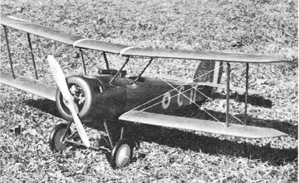
June 1971 edition of American aircraft Modeler. Joe Hankes' 33"
wingspan version of this World War I biplane is in the manner
of the late 1960s very solidly constructed in order to withstand
the grueling pounding of internal combustion engine powerplants.
With a little judicious material substitution the airframe weight
could be whittled down considerably.
Sopwith Pup
By Joe Hankes
|
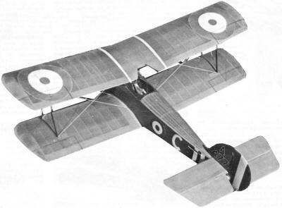
Fly it with small digital, Galloping Ghost, or go free
flight! Any way, it flies slowly and looks real.
|
The air war, during WW I, was waged on a month-to-month basis.
From 1914 to 1918, an aircraft design was effective for about four
months. A plane gradually built up to its peak of operation, stayed
there for about four to six months, and then slowly declined into
obsolescence.
In 1915, the German Fokkers, equipped with a machine gun which
fired through the propeller, were knocking down Allied planes with
ever-increasing regularity. A ship capable of combating them was
desperately needed. The Sopwith Aircraft Co., Ltd., worked feverishly
to replace their now-obsolete Sopwith 1 1/2 Strutter. Finally, in
January 1916, the plane which was to become known as the Pup first
flew. By February 6, 1916, acceptance papers were signed and production
of this little jewel began.
The Pup, which spanned 26 1/2 ft., was a much smaller plane than
the 1 1/2 Strutter. Using an 80-hp Le Rhone engine, its all-up weight
was 787 lb. Later, performance was bettered with a 100-hp engine
at only a slight increase in weight.
Early in March, the new planes started to reach the Front. Pilots
in the English Sector, who were the first to receive the Pups, were
jubilant over their performance. They were easy to fly as compared
to the Camel, which had bad spin characteristics. This little Pup
could take off with a run of only 100 ft. and came in for a landing
at only 30 mph.
The plane got its nickname from the pilots who considered the
Sopwith 1 1/2 Strutter the Dad, and the new plane the Pup. The British
brass thought that Pup was an undignified name and gave orders not
to use it. But the order was never heeded.
The model of this jaunty and frisky little plane was designed
with pulse proportional (Galloping Ghost) in mind. Wing loading
comes to only 11.4 oz. per sq. ft., since the total weight is 24
oz.; total wing area, 394 sq. in. An Enya 09 RC engine does a respectable
job of flying the plane in scale-like fashion.
The large control surfaces may cause some eye-popping at first,
but only the inner holes on the Rand actuator and the outer holes
on the control horns are used. Total throw is about a half an inch.
Those who are brave can use full throw, put in a 15 engine, and
get some real combat action.
The Pup is a fine fun flier. Its dimensions are not exact enough
to win a scale contest but, when that tail lifts on the takeoff,
and the ship gently lifts into the air, that's modeling at its best.
Construction
|
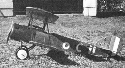
With reasonable nose and tail moments, the Pup has always
been a modeling favorite.
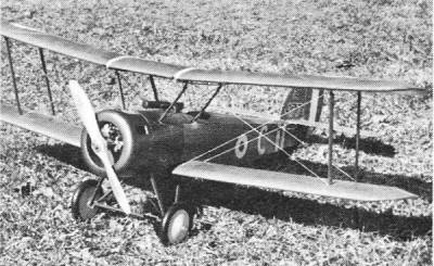
While author made a built-up balsa cowl, an aluminum
kitchen pan also might work.
|
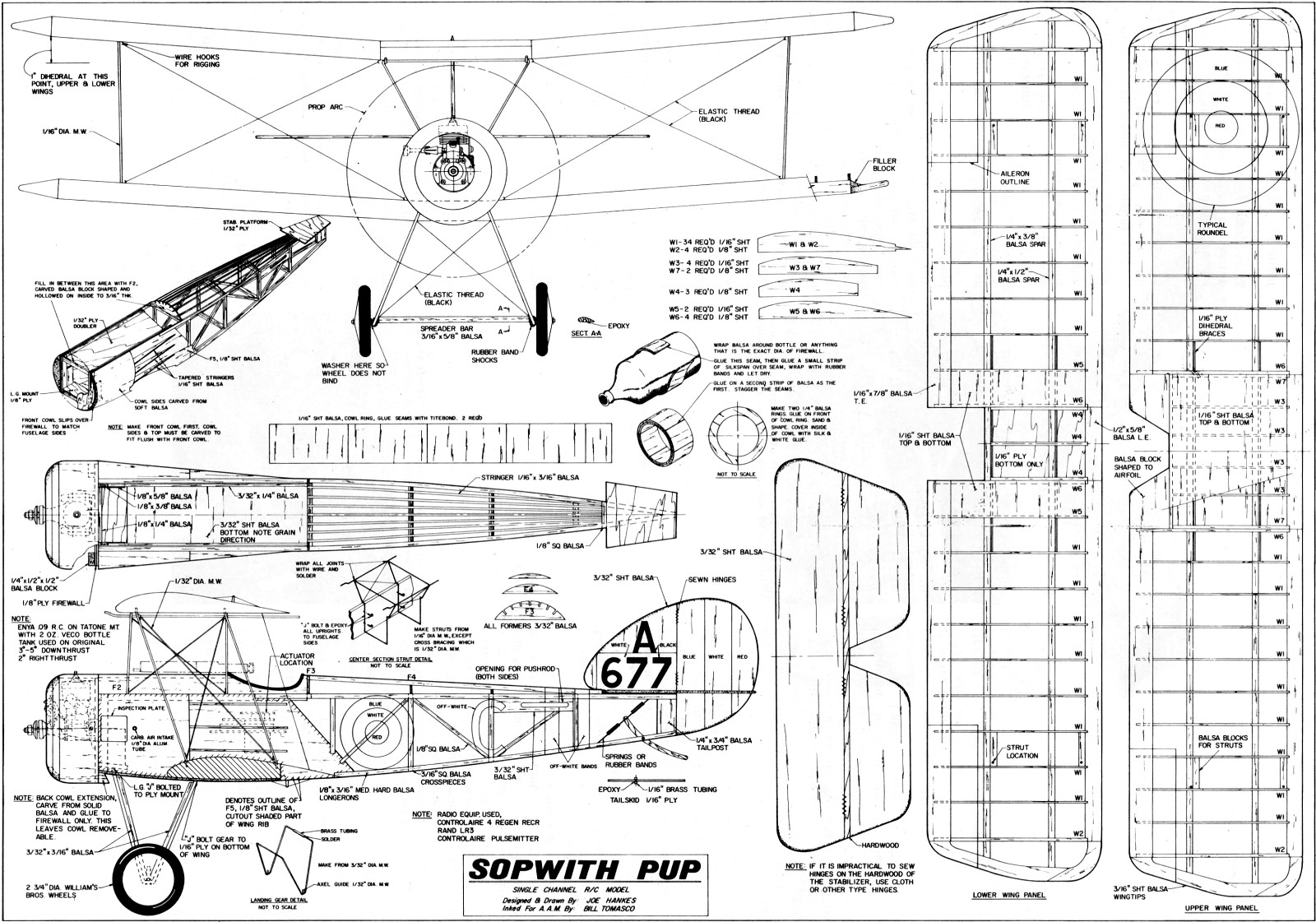
Fuselage: Cut out 2 parts of F5 from a firm grade of 1/8" sheet
balsa. Layout the remainder of the side view, using the balsa size
indicated on the plan. Glue each joint well with white glue and
let dry overnight. Make the other side view the same way.
Join the sides with the cross-members. I usually sketch the top
view on my building board and assemble the sides directly over it.
Cut out F3, F4, and F5 and cement or glue to the fuselage. Next
install the stringers.
Cut out the firewall. For an .09 engine, 1/8" ply will do, but
3/16" ply is more versatile and can be used with the larger engine.
Use epoxy to fasten the firewall to the fuselage and let set overnight.
The firewall must be exact in size.
Find a can, bottle, or anything the same diameter as the completed
firewall for construction of the cowl. Details are covered on the
plan. Note that two layers of balsa will form the ring. Seams on
the two layers are staggered, but the grain must run the same way.
Add the 1/4" balsa rings in front. Let dry, then carve and sand
to shape. Silk is glued on the inside ring part of the cowl to add
strength and rigidity. Do not glue any silk where the rear edge
of the cowl fits on the firewall. It might make the fit too tight.
Carve and sand the side blocks behind the cowl, but do not glue
them in place. Next carve the top of the fuselage in one piece and
hollow it out to about 3/16" thickness. It fits in the space from
the rear of the firewall to the rear of the cockpit.
Bend and shape the center section struts. Note the 1/32" music
wire cross-bracing. Solder all joints. Then line the inside of the
fuselage in area F5 with 1/32" ply, using contact cement for adhesive.
Fit the landing gear mount to fuselage and epoxy well. Add the
blocks in the corner to attach the mount to the firewall securely,
since this area is one of great stress. Install the center section
struts to fuselage using J bolts and epoxy well. Glue cowl blocks
to fuselage side, then add the stringers. Make the tail skid as
shown. A wire one would do, but this one duplicates the real one.
Put a 1/8 x 1/4" strip inside the fuselage along F5 (on top of the
fuselage) to act as a stiffener. The fuselage is then complete.
Stabilizer and Rudder: The stabilizer and rudder are cut from
light C grain stock and all the edges rounded. Use hardwood for
the elevators. Attach firmly, using epoxy only. I used heavy dacron
thread to sew on the hinges, but any good hinges may be used. They
must operate freely since pulse flying will not tolerate any stiffness.
Wings: The center section of the lower wing is built only from
the leading edge to the rear spar, the rest is omitted. This section
must key into the wing saddle accurately and its bottom is covered
with 1/16" plywood. On the top wing, the center section is covered
top and bottom with 1/16" balsa. I key the front of each rib into
the leading edge about 3/32" because it adds considerable strength.
When both wings are complete, sand thoroughly to make a smooth covering
job.
Covering: For a more realistic effect, I used silk, which must be
shrunk with water to draw it taut. However, any covering material
desired may be used.
Doping: To keep the plane light, I used five coats of 50-50 butyrate
dope clear. For a tinted coat, Rit dye can be blended into the dope
as follows. Soak the yellow dye in a small amount of water and strain
through a nylon stocking. Do the same with the cocoa brown dye.
Then mix the two, using mostly yellow with the brown as a tint.
Stir in an amount of denatured alcohol equal to the liquid tint.
Mix with the dope and spray evenly over the clear dope finish. Colored
dope could be used, but go easy on it to prevent excessive weight
buildup near the tail.
The authentic color of the cowl and fuselage top is aluminum.
Struts may be a clear finish such as that produced by an orange
shellac. Paint on the roundels, or use decals. Squadron markings
differed greatly, and any authentic color scheme may be used.
Assembly: Bend the 3/32" music wire landing gear as shown. Epoxy
the lower wing onto the fuselage and let set overnight. Incidence
must be 0 degrees. Jig up this assembly so that it lines up from
the top, side, and front. Then J-bolt the landing gear in place.
Fill in the bottom of the fuselage with 3/32" sheet balsa and dope
to match the rest of the paint.
Cut and glue on the stabilizer platform, then the stab. When
putting on the rudder and vertical fin, cut two notches into the
top of the stabilizer. Make two corresponding notches on the vertical
fin and cement in place. The vertical fin must be cut about 3/32"
longer to allow for notching.
Make the wing struts. Rubber band the upper wing into place,
and install the struts and rigging. My rigging was elastic thread
inked black and removable for flying.
Install the Tatone engine mount, centering the crankshaft on
the center of the cowl. Cut out appropriate openings for the engine
head and the exhaust. A small hole may be put in the bottom of the
cowl for an oil drain. Make the opening around the engine head a
little larger to insure adequate cooling. The two-oz. Veco tank
lies horizontally behind the firewall above the radio equipment.
Radio gear and its installation is up to the individual. I used
a Controlaire 4 receiver, with a Rand pack and it operates flawlessly.
Carve and sand the spreader bar and groove out for the 3/32"
music wire axle. Epoxy it in place. When set, rubberband the bar
to the landing gear. Slip on the wheels and solder the retainers.
The scale-size wheels are 2 3/4" (I used 3" because that is all
that was available). The top of the fuselage from the firewall to
the rear of the cockpit is fastened on the front by a music wire
pin through the firewall into the balsa, and in the rear by a bolt
to a crosspiece in the fuselage. The crosspiece is located near
the front of the Rand actuator.
Flying
Check out the pulse system so that the elevators and rudder pulse
are in neutral. Hang the airplane by a string located at the center
of gravity and correct any wing heaviness. When the CG is within
bounds, the Pup is ready to go.
With the Enya going full blast, I began the first flight by signaling
for the release. I gave it a bit of forward stick and up came the
tail. After almost 75 ft., the ship lifted and climbed out. Since
it always wanted to turn left, a little more right thrust was needed.
After about a minute of flight, I eased the ship onto the final
and throttled down. With a little trim, in it came. There was a
decided ballooning tendency on the flare-out on landing. Take it
easy on the control movements.
Biplane fans have a lot of enjoyment in store for them. If flying
with three servos, use 3/32" wire on the center-section struts.
No rigging or struts were used for flying; however, they could be
if made light in weight.
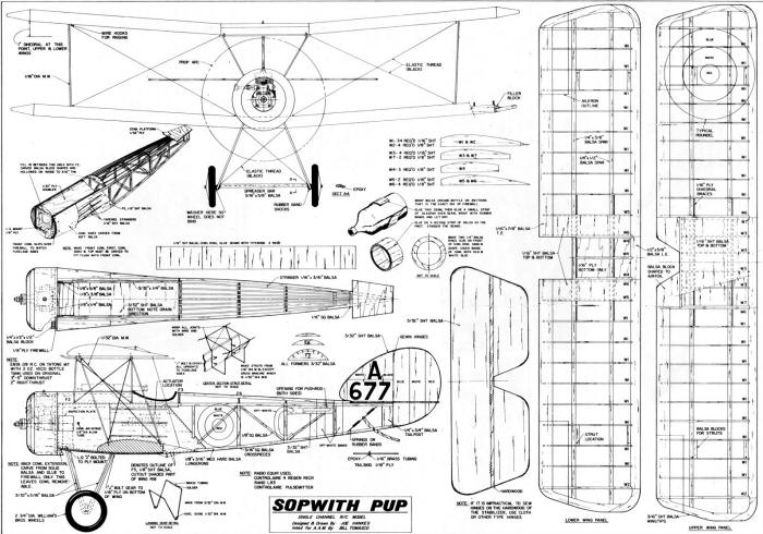
Sopwith Pup Plans
Notice:
The AMA Plans Service offers a
full-size version of many of the plans show here at a very reasonable cost. They
will scale the plans any size for you. It is always best to buy printed plans because
my scanner versions often have distortions that can cause parts to fit poorly. Purchasing
plans also help to support the operation of the
Academy of Model Aeronautics - the #1
advocate for model aviation throughout the world. If the AMA no longer has this
plan on file, I will be glad to send you my higher resolution version.
Try my Scale Calculator for
Model Airplane Plans.
Posted December 13, 2014
|