|
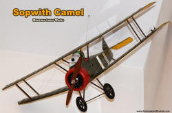 Melanie gave me a Peter Rake-designed Sopwith
Camel from Manzano Laser
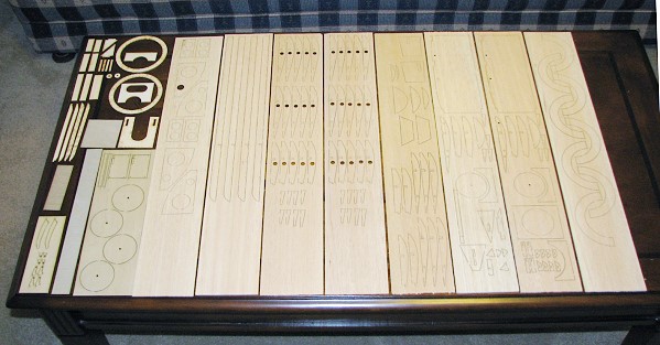
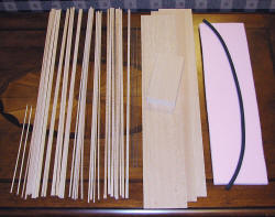
Works short kit for Christmas 2008. The entire building process has been documented
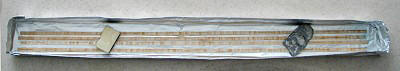
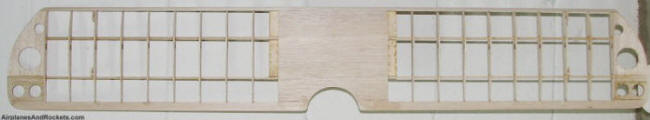
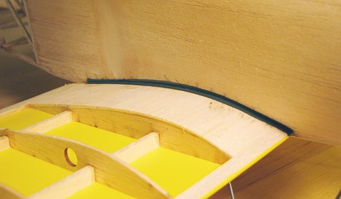
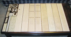
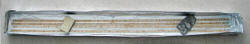
here. The laser cut parts are very nice, as can be seen in these photos. BTW, if
you can't get enough Sopwith Camels, here is my
Cox Sopwith Camel. Melanie gave me a Peter Rake-designed Sopwith
Camel from Manzano Laser
Works short kit for Christmas 2008. The entire building process has been documented
here. The laser cut parts are very nice, as can be seen in these photos. BTW, if
you can't get enough Sopwith Camels, here is my
Cox Sopwith Camel.
See the silkspan and dope covering tutorial video (April 2010).
Updated December 4, 2009 | Updated
November 5, 2009 |Updated
October 12, 2009
 There
are a couple places you can go to read construction articles on the Sopwith Camel,
but they are for radio control. My Camel was originally going to be built for control
line, so I figured it would be worth including some additional information here.
I have since then decided to use a 3-channel R/C setup. I planned at first to use
the recommended Graupner GR170323 motor/gearbox combination, but have since settled
on an E-flite Park 370 brushless outrunner motor to get the extra power. Either
a 2-cell, 1500 mAh LiPo or a 3-cell, 1300 mAh LiPo battery will be used. Using an
APC 10x4.7 e-propeller and the 3-cell LiPo, the thrust-to-weight ratio on a full
charge well exceeds 1:1. There
are a couple places you can go to read construction articles on the Sopwith Camel,
but they are for radio control. My Camel was originally going to be built for control
line, so I figured it would be worth including some additional information here.
I have since then decided to use a 3-channel R/C setup. I planned at first to use
the recommended Graupner GR170323 motor/gearbox combination, but have since settled
on an E-flite Park 370 brushless outrunner motor to get the extra power. Either
a 2-cell, 1500 mAh LiPo or a 3-cell, 1300 mAh LiPo battery will be used. Using an
APC 10x4.7 e-propeller and the 3-cell LiPo, the thrust-to-weight ratio on a full
charge well exceeds 1:1.
The instructions and plans are very sparse, and leave a lot to the imagination
regarding the actual construction, so there are photos here that you will not find
elsewhere. A lot of balsa sheeting, wire bending and soldering, and balsa carving
and sanding is required. While there are people out there gifted with an ability
to figure it all out even the first time around, many will appreciate some help.
Hopefully, this content will take the edge off the difficulty in getting through
the process. The old says goes that a picture is worth a thousand words, and for
model building that is definitely true. Here are a few thousand extra words.
New photos will be added as building progresses.
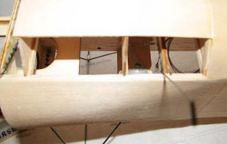
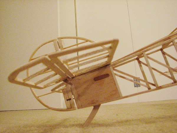
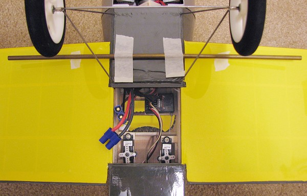
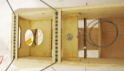
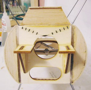
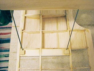
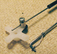
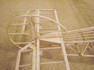
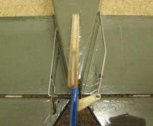
The photo below shows the bellcrank mounted in the fuselage. I plan to attach
the wings permanently, so the bellcrank faces upward for access through the cockpit
for maintenance. Lead-out lines are coiled for now. You can also see how the landing
gear wire is laced and epoxied to the plywood mounts. After the bottom balsa sheet
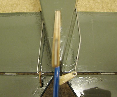
is on, filler will cover the wire. There is another shot of the bellcrank, only
this time from the top. You can also see where the the cabane struts are laced and
epoxied to the formers.
 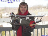
 
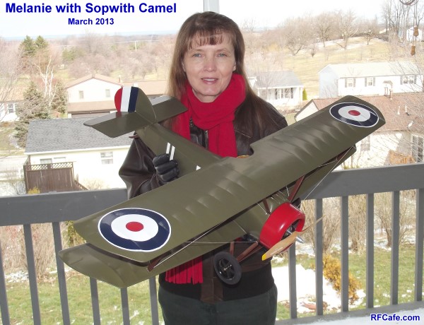
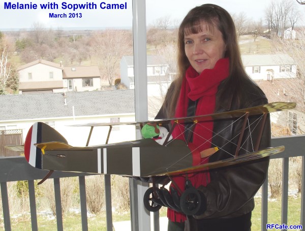
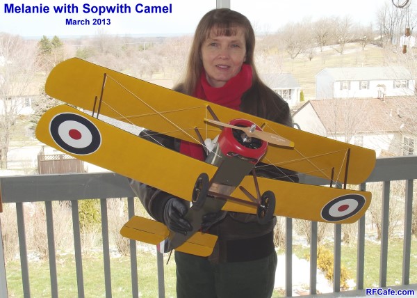
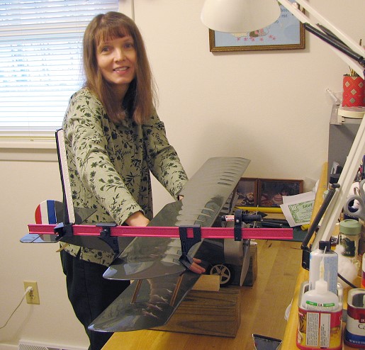
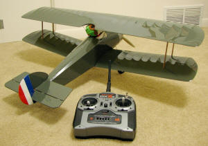
Melanie with the Manzano Laser Works Sopwith Camel - Set up for
electric-powered control line.
March 2013 Update
I finally completed the wing repair and totally refinished the entire Camel.
About a pint of acetone and lots of paper towels were used to wipe the color coat
of dope off the entire airframe. Then, a couple coats of clear were applied, and
a couple coats of white base color. Sanding was done every other coat. Even with
the white base, it took five coats of yellow to get a good opaque color. Just two
coats of olive drab green were needed, and three coats of Insignia red. Prior to
painting, two additional coats of white were applied in all the areas where white
would be needed in order to avoid having to brush many coats of white over color.
When the weather warms up, I plan to spray a light coat of clear over everything.
Construction Photos
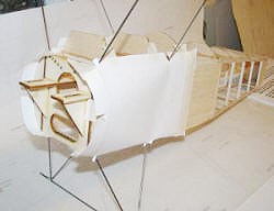
I have found that it is easier to get the balsa sheeting right for compound surfaces
by first making paper templates. The ones shown below were taped tightly to the
frame, then a pencil was used to trace the edges. I cut the templates with scissors,
then used them to draw the outline on the balsa sheeting. Cut them just slightly
oversize, then sand to fit. For installation, I glued the straight, flat edge toward
the rear of the fuselage, then wetted the top surface with water and used masking
tape to pull the sheeting tightly to the formers and fuselage. After it dried, I
lifted the sheeting enough to apply glue, then taped everything back in place and
let the glue set. The process was repeated for most of the curved sheeting pieces,
including the front fuselage top pieces (I did it in three separate pieces).


Vertical fin & rudder laminations - a vessel for holding
the lamination strips
was formed out of tin foil, then weights held the balsa
under the alcohol.
Here is the completed side sheeting, the rear top sheeting, and the front top sheeting.
The rear top sheeting (over the cockpit area) was first cut a little oversize, then
one edge was glued to the fuselage side. The top of the sheeting was wetted, and
then masking tape held the sheeting to the formers while it dried. I then sanded
the loose side to make it mate with the other fuselage side. I personally do not
like having to use a lot of filler for sanding later, so I put a little extra effort
into getting a good fit. In order to provide a good gluing surface for the front
fuselage top sheeting, I cut an 1/8" wide strip of 1/16" thick balsa that matches
the curve of the rear cockpit former. Otherwise, you would need to have the sheeting
join within the width of a single piece of 1/16" balsa former.
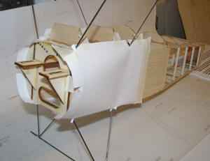
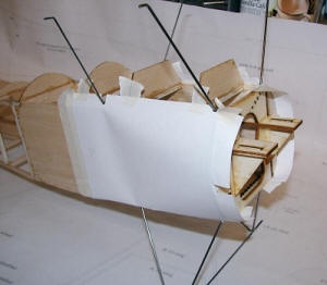
Instructions for building the cowl are equally ambiguous. Nothing indicates that
the thin strip of plywood that gets wrapped around the perimeter of the cowl should
not go all the way around, but it does not. The first step is to cut 1/8" balsa
stick separators that set the proper distance between the plywood cowl rings. I
used five separator pieces. Be sure to get everything square. Next, wet the outside
surface of the thin plywood and wrap it around the rings. I used clamps to hold
it in place. Once dry, remove the plywood, apply glue, and clamp it in place until
the glue sets. Sand both side flush once dry. Finally, the 1/8" balsa half-circles
(8 of them) are glued to one face of the cowl ring. I shifted each set of halves
by 90° in order to keep all the joints from being in
the same location.
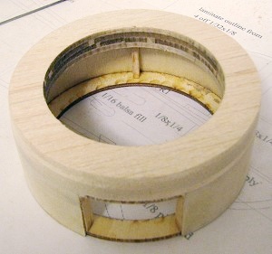 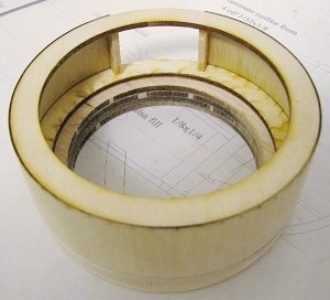
Cowl assembly, prior to cutting away bottom area and final shaping
Below are a couple photos of the
wings being rigged
on the Sopwith Camel.
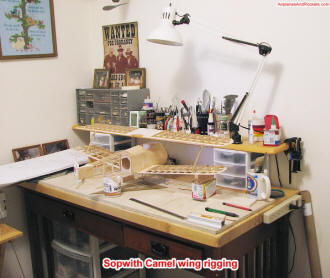
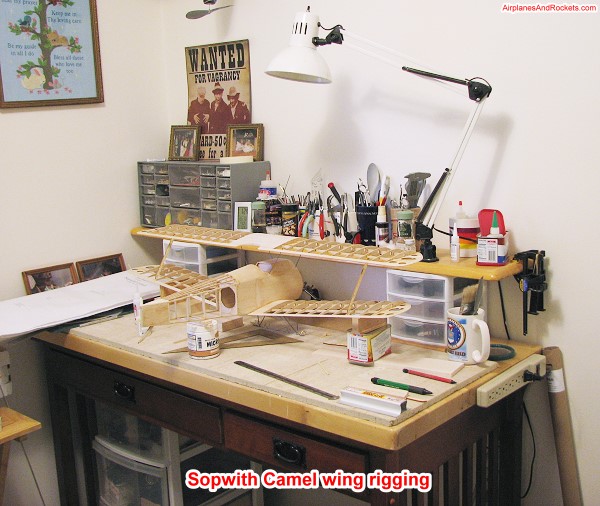
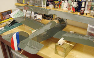
This is the Sopwith Came on the workbench during the wing rigging procedure.
Per the instructions, the top wing was attached first, since the dihedral of the
bottom wing is set by the length of the wing struts. Note that while I originally
planned to make the Sopwith Camel a control line model, I have decided instead to
do 3-channel radio control using rudder and no ailerons. Therefore, I have configured
about twice the normal dihedral in the bottom wing; the top wing is still flat.
That's not too much of a deviation from scale, so only the true Camel fan will suspect
anything is amiss. The first step is to fix the fuselage in position and hold it
there rigidly. I used large T-pins crossed across the landing gear wire to stake
the model to the building board. A prop was placed under the rear fuselage to make
the fuselage bottom where the lower wings attach level with the board.
Next, the top wing was attached by sliding the cabane wires into the plywood
saddles. It took a while, but I kept measuring, removing the wing to bend the wires,
and re-installing the top wing to get everything exactly aligned (equal distance
from wingtips to rear of fuselage, wings level with building board). Once satisfied,
I removed the wing, sanded and cleaned the music wire cabane struts with alcohol,
then squirted thick CA into the plywood saddles and re-mounted the wing. Finally,
re-check alignment and let the glue set. On my Camel, I used a small jeweler's file
to file a couple small grooves in each of the strut wires where they are captured
inside the plywood saddles just as an extra gripping point.
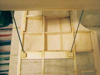
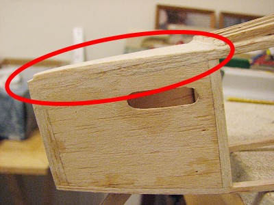
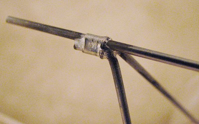
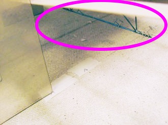
Here is a close-up that shows how the cabane struts are attached to the top wing
using 1/8" aircraft plywood that has a groove filed in the middle to accept the
music wire. Make the slot is a snug fit that the wires can be slid in and out of
during adjustment.
Aligning the bottom wings: Use a large square or triangle contacting the trailing
edge of the top wing to mark the location of the top wing on the building board
- one mark very near the fuselage and then another out near the tip. Apply masking
tape and mark the tape (keeps the board clean). Then, using the 1/8" dowel stubs
in the bottom wing root rib, slide it into place against the fuselage. Use the square
or triangle right next the fuselage to mark the location of the bottom edge trailing
edge on the building board. Do both left and right wing halves and verify that the
distance from the top wing mark to the bottom wing mark is the same on both sides
(or within a small fraction). Remove the bottom wings and place a piece of
masking tape on the board out near the tip where the top wing mark is located. Place
a mark on that tape the same distance as the ones near the fuselage. Do the same
for both sides. Now, reattach the bottom wing halves and use the square or triangle
to align the trailing edges. Prop the wingtips up using the rear wing strut as a
gauge. Measure to make certain that both halves are at the same dihedral angle.
Re-verify the trailing edge alignment, then flow some CA glue into the wing mount
areas at the fuselage interface. Leave the fuselage attached to the building board
while fitting the outer wing struts. Be sure to sand to shape and verify that the
angle of attach (incidence angle) of all wings are correct before gluing the struts.
November 5, 2009 Update
Well, it is November 5, 2009, and my Sopwith Camel is just about ready for covering.
Although I was going to do a silkspan and dope job when the Camel was going to be
configured for control line flight, I am now planning to use Monokote - olive drab
everywhere except on the bottoms of the wings and rudder. The photos below show
details of the open framework, radio and battery installation, motor, wheels, wing
strut attachment points, elevator and rudder hinged surfaces, etc. As mentioned
earlier, the plans and instructions are very sparse so I was sure to take lots of
photos along the way for the benefits of others.
|

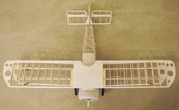
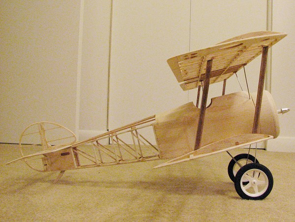
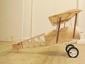
Peter Rake Sopwith Camel open framework,
ready for covering.
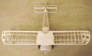
Top view of the framework.
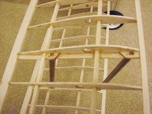
Detail of wing strut attachment (stained & lacquered). Note
that 1/4" wide strips of 1/16" balsa have been added to the side of the strut ribs
(top and bottom wing) to provide an anchor for Monokote.
Monokote is applied from fuselage out to struts, then from struts
to wingtip.
Horizontal stabilizer mount sanded to correct angle of attack.
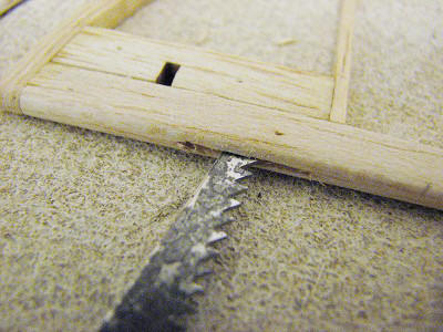
Using a small X-acto saw blade to create proper size hinge slots.
Carbon fiber pushrod - E/Z Link on servo end, custom retainer
on control horn end.
|
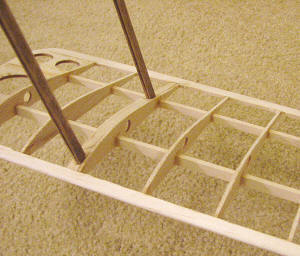
1/16"x1/8" balsa strips were glued diagonally across all the
rear fuselage frame members. The added rigidity is amazing (no twisting of the empennage),
and the weight is negligible.
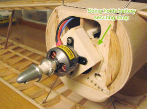
1/8" plywood motor mount and string used to hold the battery
pack retaining strap in place.

Empennage details showing hinged surfaces.
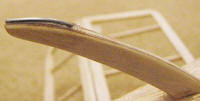
Tail skid with music wire super glued on bottom for durability.
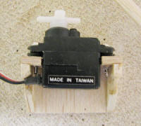
HS-55 servo in custom mount.

Landing gear solder joint.
|
November 22, 2009 Update
Covering with Monokote has begun. Yellow is used on the bottoms of the wings,
and olive drab is used everywhere else except on the rudder (which is bleu, blanc,
et rouge). Decorations (roundels, etc.) will be added after the first few flights.
That's one of the many benefits of electric flight - test flights can be made without
fear of rendering the finish unable to accept paint or iron-on covering because
of oily exhaust residue.
For the lower wings, a 1/4" wide strip of olive drab Monokote was attached at
the junction between the wing and fuselage in order to accommodate a not-so-perfect
joint later. A paper template was made for the top of the lower wing halves to get
the contour of the fuselage interface right without having to trim the Monokote
at the fuselage during the ironing process. Likewise, a paper template was used
to cut the contour of the top of the wing halves into the fuselage side covering
prior to ironing. It worked out very well.
|
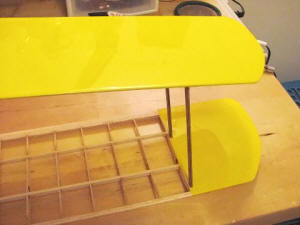
Covering wing in sections.
|

1/4" wide strip of Monokote ironed into junction between lower
wing and fuselage.
|
December 4, 2009 Update
My Camel is now fully covered, but without any trim markings other than the bleu,
blanc, et rouge stripes on the rudder. An attempt to wrap the cowl in Monokote did
not work out well enough to keep. Using lots of heat from the heat gun, I was able
to successfully stretch the Monokote around the small radius to where there were
no wrinkles anywhere, but it was so thin that it was translucent and you could see
the wood underneath. So, I peeled off the Monokote and covered the cowl with medium
grade Silkspan and dope. A few coats of clear were applied and sanded, then a couple
coats of Testors silver dope finished it.
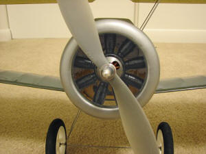
The front half of the dummy radial engine provided with the kit has been painted
and installed in the cowl. The E-flite Park 380 brushless motor pokes out neatly
through the crankcase area. As suggested in the instructions, the cowl will be held
to the firewall with a couple small dabs of silicon cement.
|
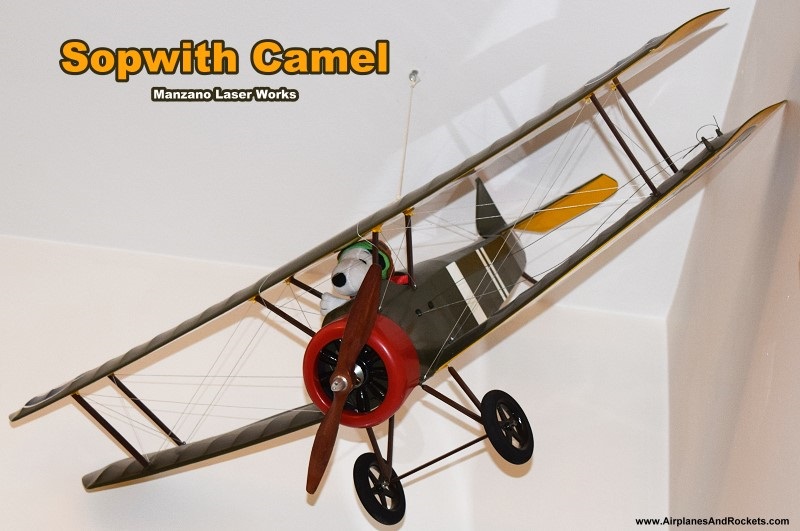
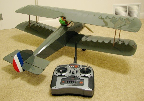
Manzano Laser Works Sopwith Camel ready for its maiden
flight!
|
Adjusting the incidence of the top and bottom wings took a fair amount of work,
but was worth it to guarantee that no surprise rolling and/or stalling tendencies
would be experienced! The first step was to block up the Camel on the lower wings
near the fuselage, set to be parallel with the workbench surface. Then, measurements
were made at the lower wingtips to get it level from side to side. The distance
from the workbench to the trailing edge was measured near the fuselage, and that
was used to adjust the angle of the wingtips. About 3/32" of washout (LE lower than
TE) was set at the tips to help tame the stall behavior. Changes were made by twisting
the wingtips while using a heat gun to re-shrink the Monokote to hold the shape.
the fuselage needs to be held rigidly in place whilst twisting. The top wing was
already set parallel to the bottom wing during the installation on the cabane struts,
so only the top wingtip incidence needed to be checked. I used ruler measurements
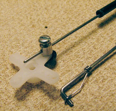
for that as well, and set the same amount of washout in the top wingtips. A final
check was done using the Great Planes laser incidence meter, as shown in the photo
below. It confirmed my measurement. I did not use the meter for initial adjustments
because its weight was barely tolerated by the relatively flimsy wing structure.
I was careful to configure the meter's distribution of weight to not cause the wingtip
to tilt to the front of rear and thereby affect the readings.
|
Sopwith Camel sitting on leveling blocks for wing incidence
adjustment .
|
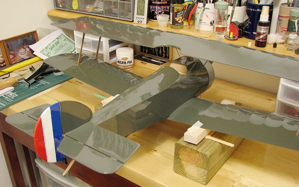
To balance the Sopwith Camel, I taped a 1/4" round brass tube at the center of
gravity point per the plans (2.25" back from the firewall). The tube was then set
atop wooden block to get the wheels off the surface, then weight was added as necessary.
Be sure to hold the airframe in a font-to-back level position before testing to
see which way it is going to tilt, or you can get a false reading. I was a bit disappointed
when it cam time to balance the Camel in that it required 3.5 ounces of dead weight
in the front of the cowl. I hate that! Prior to adding the weight it was at a respectable
19.2 ounces; now it is sitting at 22.7 ounces - yuk. Well, it is better to be heavier
than planned than to be tail heavy and destroy the craft.
|

1/4" brass tube taped at balance point.
|
Pushrod connections at rudder and elevator - wire retainer
is bent from a pen spring (right)
|
Here is the ready-to fly wing loading:
Wing Area: 2 x 36" x 5.75" = 414 in2 = 2.88 ft2
Weight: 22.7 ounces
Wing Loading = 22.7 / 2.875 = 7.90 oz/in2
A lot of Park Flyers run in the 5 - 6 oz/ft2 range, so she definitely
will not fly like a Park Flyer, but then the Camel is not advertised as such. To
the other extreme, the Great Planes electric Cub is rated at 16 - 17 oz/ft2,
so she should do much better than even a notoriously docile Cub. Now, I just need
a good day...
Posted 8/30/2009
August 2010
A few months ago while painting the bedroom where my model building occurs, I
was stupid enough to place the Sopwith Camel on the floor where I thought is would
be safe from damage. I have a rule of never putting a model on the floor if I'm
not going to be working on it, then back on the bench or wall it goes. Well, as
bad luck would have it, a drawer that had been removed and stood on end tipped over
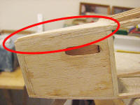
and cleaved a chunk out of the lower right wing panel. I spent a good two or three
days mentally flogging myself for that instance of idiocy. I have finally gotten
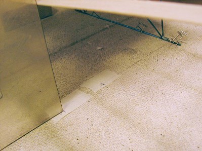
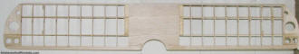
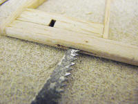
around to affecting a repair. I cut off the ragged silkspan, and trimming and sanding
the spar and trailing edge, then made a template for the ribs. Rather than try to
cut out the good portion of the damaged ribs, I decided to place the replacements
next to the existing ribs. The photo below shows the repair.
The next step will be replacing the silkspan. Unfortunately, the roundel on the
bottom of the wing has an area that needs to be re-painted. It might be a while
(or never) before that gets done.
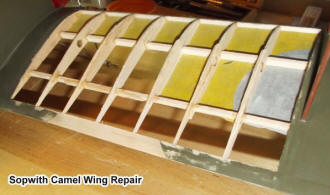
Sopwith Camel Lower Wing Repair
See photos at top of page of repaired and totally repainted Sopwith Camel.
Posted June 5, 2023
(updated from original post
on 2/11/2012)
|