|
Airplanes
and Rockets visitor Rob K. requested that the article be posted
for the Small-Fry Special, a 1/2A-powered beginner's control-line
model. Its all sheet balsa construction with the engine mounted
using rubber bands makes the Small-Fry Special easy to build and
repair, and provides a extra helping of forgiveness if you happen
to botch a landing. The wing even has ailerons glued permanently
in position for a right roll to help keep the lines tight. Photos
and flying instructions are included in the article from the May
1969 edition of American Aircraft Modeler. Small-Fry Special
For about $3, less its 049 engine, you can quickly build
and fly this sturdy control-line trainer. Howard
C. Mottin
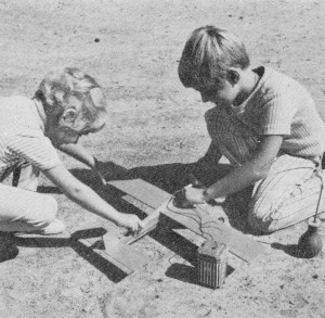
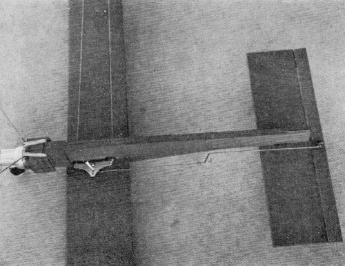
With this reliable trainer the kids can go flying by themselves.
Today's easy-starting 049 engines are no problem for a youngster.
Flyer's sister holds.
Balsa models are painted with model airplane dope so that the
fuel and exhaust do not seep into the wood. Use two coats of
clear and two coats of color.
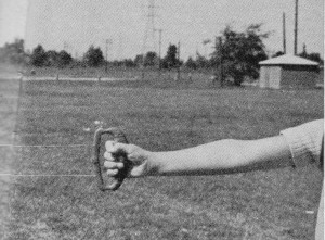
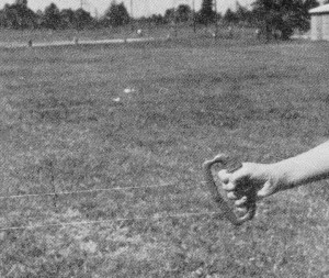
How you hold control handle is important. Keep your arm straight
at all times. Lift arm for up, lower for down. Level is neutral.
Line on top is for up, line on bottom for down. Raising your
arm causes pull on up-elevator line and releases the other line
slightly, causing the model to climb.
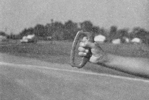
Down-elevator is the opposite of up movement. Positions are
a bit exaggerated here. Arm motions only prevent over-controlling.
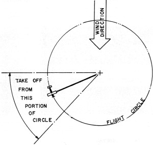
Take off downwind so that model is airborne with wind keeping
line tight.
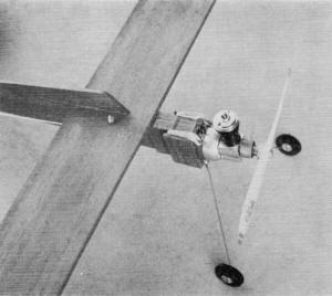
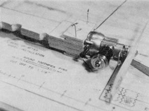
Engine is held in place with rubber bands looped around
the mount and toothpick sections which key the motor on the
nose. It will come off harmlessly in a bad crash, but is secure
in flight.
Put the engine on the toothpick studs to keep them properly
aligned while assembling the nose doublers. Be careful to keep
glue out of the intake screen on the rear of the engine.
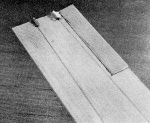
Using model cement, glue short lengths of 1/2"-wide pinking
tape to the top side of elevator and stabilizer with plenty
of overhang. When dry, fold down and across to opposite half,
then glue again.
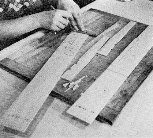
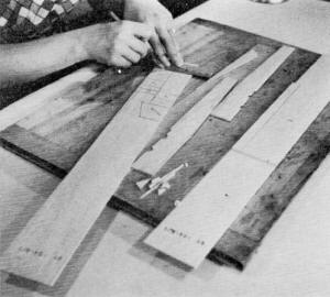
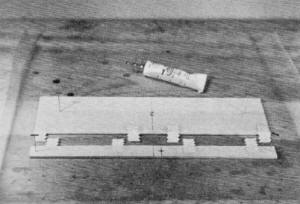
Construction begins with cutting the parts out as per the
plans. Only two sheets of balsa are needed, model airplane glue,
sharp knife, ballpoint pen, and soft building board.
Leadouts from the bellcrank leave the inboard wing tip through
eyelets or short lengths of tubing. These must be securely glued
and gauzed to the wing. Note the aileron position.
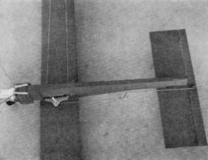
Wire pushrod between bellcrank and control horn on elevator
has a double bend at its middle so that it can be adjusted for
neutral elevator position with bellcrank parallel to fuselage.
So you want to fly control-line models? Then try a rugged Small
Fry for an easy, economical way to start. The parts for the basic
model, namely the two pieces of 1/8-in. balsa, can be bought for
under a dollar. The rest of the hardware items can be purchased
for around $1.00, making the price for the works (less engine) around
$3.00, including paint. A 1/2A or 049-size model can
be difficult to fly because of its small size, and because it flies
on shorter lines. Contrary to popular belief, larger models, say
a 35-size, are a lot easier to fly, but they are also a lot more
expensive. Thus, thousands of inexpensive 049 engines are sold every
year, only to be stored in a drawer when the first building project
ends up in a pile of balsa, or worse yet, is never completed because
of the building time involved. The first thing to
learn in the model plane hobby is to take enough time to perform
each step properly. Something left undone or hurried over will end
only in disaster. If you follow the construction steps in this article
you will end up with an airplane that does fly well. This model was test-flown by my 5-year-old daughter! It did take
a few crashes before she flew successfully. We went through five
versions before we came to the final one, which is a cinch to fly.
If set up as described, it will fly for anyone. Another favorable
point is that it is rugged enough to survive a few mishaps, and
easy to repair or rebuild. Simple parts make it easy to repair.
But in case of a total break-up it's not hard to build a new one
reusing the same hardware. The important thing is not to become
discouraged if your first few attempts at flying result in failure.
Remember that even those of us who have been flying for years crash
occasionally. You will crash occasionally when you
are starting out. Remember what you did wrong and correct the mistake
on your next flight. Not to scare anyone away, these are just facts.
It is possible to fly successfully right from the start. All that
is required is to remember two controls, Up and Down. In between
these is Neutral - where the plane should be flown. It's that simple.
Just give a little up to take off and, once airborne, come back
to neutral and fly the whole flight. Now let's get
started. First requirement is the Cox 049 engine. I bought a Cox
Baby Bee for my model. I also used an old engine from a long-gone
plastic model. If you already have an engine you're all set. If
not, I would recommend purchasing a Cox Baby Bee or Quiet Zone engine.
These are available almost everywhere from hardware stores to department
stores and at all hobby shops. While you're at the local hobby supplier
buy the rest of the materials on the list and you are ready to start
building. A brief note on the balsa wood: try to get
a piece that is not badly warped. Hold the board on its side and
sight down the long edge. In this way you can see all the bends.
Pick a board that is fairly flat or that has a gradual curve, not
one that looks like a roller coaster. Besides the
building supplies on the list there are a few other items you will
need. If this is your first building project, you will need a knife
(X-acto No. 8 will be adequate), glue (Testers B, Ambroid, etc.),
a pack of model "T" pins, and a straight-edge (this can be the metal
edge of a common dime-store wooden ruler). Other items are pliers,
wire cutter, building board and sandpaper. An optional item that
is nice to have but not mandatory is a carpenter's combination metal
square. It can be purchased for under $1.00 at just about any hardware
department. It also can be used as a straight edge.
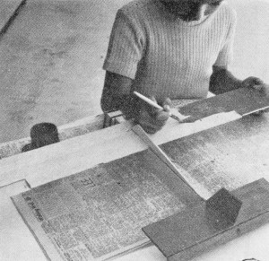
Construction: Layout all the parts on the two 1/8"
balsa sheets. A ball-point pen is used to draw these, but do not
press too hard. The sketches show how to layout these parts. It
will help to number the nose-pod pieces to avoid confusion. The
dimensions for the various pieces can be obtained from the side
and top views on the plan. When drawing the lines across the sheets,
use the square to keep these perpendicular to the sides. When the
layout is completed, cut out all the balsa parts using a sharp hobby
knife. A large balsa piece will be left over. Save this for repairs
or your next plane. We are now ready to begin assembly. I usually build the fuselage first and, while this is drying, work
on the tail or wing assemblies. Lay down a small piece of wax paper
(approx. 12" square) on your building board. This will prevent the
parts that will be glued together from sticking to the board. The
first step is to glue the two fuselage sides and the front center
(No. 1) piece together. Spread a liberal amount of glue on both
sides of the center piece and put a small bead of cement on the
tail end of one fuselage side. Then put the three pieces together
and pin down to the board on the wax paper. Put four pins through
the front section to the board, checking the alignment of all three
pieces at each step. Pry up the tail end of the fuselage side next
to the board and put a toothpick under it, so it is approximately
1/16" off the board. Pin the tail ends together with two pins.
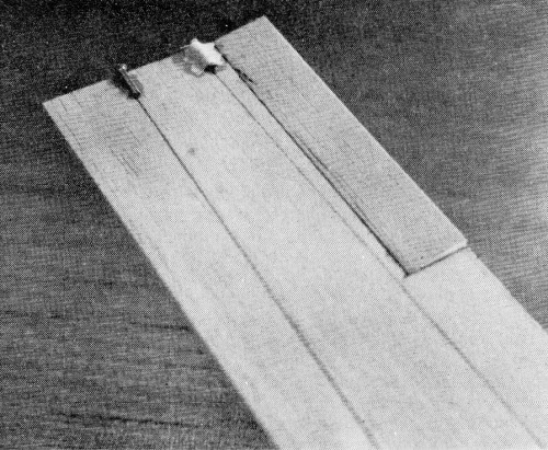
While this is drying you can start assembling the two outside
pod pieces. Take four round toothpicks and cut off to the length
shown on the plans. Now lay pieces No.4 and 5 on the building board
with the dotted lines up. The dotted lines -should be 3/16" from
the top and 1 1/16" apart. Using just the point of the knife at
an angle of approximately 45 degrees with the piece, cut triangular
grooves in these pieces centered on the dotted lines. Do this carefully,
taking several small cuts. Measure the groove between these cuts,
using the cut-off toothpick as a gauge. Stop when the toothpick
just fits in the groove and the top edge is flush. Put the toothpicks
in the slots and place the No.6 or 7 piece on top and check the
protruding part of the toothpicks for alignment, using the engine
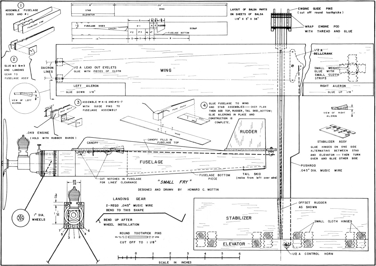
mounting holes for a gauge. MATERIALS LIST
Two sheets 1/8 x 3 x 36" balsa One piece .045 dia. x 36"
music wire 1/2A Bellcrank, Perfect #233 1/2A Control horn;
Perfect # 234 1/2A lead out eyelets, Perfect #236 Small
cloth hinges, Perfect # 202 Wheels 1" dia., Perfect #62
Miscellaneous: Round toothpicks, thread, small rubber bands (size
16), dope (fuel-proof), thinner, brush (1/2 or 1/4"), Goldberg 1/2A
handle with Dacron lines. If everything checks out,
glue these two assemblies together. If everything was not right,
make a new piece from the scrap-balsa piece. Use a liberal amount
of glue in the grooves to glue in the toothpicks and pin these two
assemblies down to the board to dry. Check the alignment of the
front edges to make sure they are flush and double-check the toothpicks
with the engine. Now take out the two pins in the front
end of the fuselage assembly and glue the No.2 piece flush with
the front. Unpin the entire fuselage assembly after the glue has
dried. Place the No. 3 piece and the 7-5 assembly and 4-6 assembly
on the fuselage and hold the front end with one hand. Use the engine
mounting holes as a gauge once again and check the mounting alignment.
Chances are that the pins will be too wide apart. But if the engine
slides on, go ahead and finish the pod assembly. If the engine didn't
fit, slide out the No.3 piece. Lay a piece of sandpaper flat on
the building board and lay the No.3 piece on it. Holding it flat
against the sandpaper, slowly slide it back and forth sanding it
down on one side. Recheck the fit after every three or four sanding
strokes until it fits snugly between the fuselage assembly and the
7-5 piece. When everything fits properly remove the engine, and
glue the No.3 piece to the fuselage assembly. While
this is setting, mark the location for the landing gear mounting
hole. This is approximately 5/8" from the front and 5/8" from the
top. One of the leftover round toothpicks can be used to start these
holes. The two landing gear wires should be made to the shape shown
on the plans. Now mount the wires to the fuselage assembly and cut
grooves so that the top of the wire is flush with the surface. The
engine pod is completed by gluing on the two outside pieces, reinforced
by wrapping with thread at the front and back. As the assembly is
pinned together, check the alignment, using the engine as a gauge.
Spread a small coat of glue over the thread and over the entire
front surface of the pod. The triangular hole in the bottom of the
fuselage can be filled in with a piece of scrap. Next
comes the assembly of the stabilizer or "stab." If you have not
already done so, cut apart the elevator and stab. With a piece of
sandpaper, round off the leading edge of the stab and the two edges
that will form the hinge line. It is easier to work with the stab
if it is pinned down to the building board. The stab and elevator
should be lined up properly and an approximate one-inch gap left
between them. Now take four of the small cloth hinges
and cut them in half. With a ball-point pen, make a small "x" at
each position where the hinge will be glued on as shown on the plans.
Then taking them one at a time, put a small glob of glue on the
"x" and press on the hinge cloth leaving about 2/3 to hang over
the edge. After these have dried, unpin and turn over the stab and
elevator and again mark an "x" where the hinge will be glued on.
This will be opposite to where the hinge material is sticking out
of the pieces. Slide the two pieces together so that all the hinges
are sticking straight up and pin to the board. Then repeat the gluing
procedure making sure hinges are tight. Now lay the
plan on the building board and lay a piece of wax paper over the
top view. The stab is pinned down to the location on the plan, and
likewise the wing. Glue on the fuselage following the location on
the plan. While this is drying you can glue on the leadout eyelets
and the wing tip weight. But remember the plane is upside down,
so glue them on the opposite ends of the wing from what you are
looking down at on the plan. The weight can be just about anything
from a flattened-out fishing sinker to a washer (about the size
of a penny). Small pieces of left-over hinge cloth should be glued
over these to strengthen them. We're now in the final
stages of construction. The canopy piece (top) and the rudder are
now glued on. Be sure and offset the rudder so the plane will have
a tendency to turn (yaw) to the outside of the circle. Cut out the
ailerons and glue in place as shown. The left aileron will be down
and the right will be up. The holes for the bellcrank and control
horn are added. They can be made using a round toothpick as a drill.
The control horn can be fastened on and a small amount of glue should
be put over the nut to keep it from working loose. Do not turn the
nut so that the balsa is squeezed together, but merely bring it
up snug to the surface. The glue will keep it tight. The bellcrank will be installed after the plane is painted. The
wheels now are added and the protruding wire bent up so they will
not slide off. Make a small wire tail skid from left-over wire and
glue in place at the bottom of the tail end of fuselage . This will
prevent the balsa from being scraped away. The one
remaining task is to paint the little gem. Since this plane will
never be a candidate for a best-finish award, there is no sense
in spending a lot of time here. Besides, at this point you probably
can't wait to get it into the air. So give it two coats of clear
dope followed by two coats of your choice of color and call it a
day. Be sure and coat the engine pod area thoroughly to keep the
fuel out of the wood. Now make a pushrod from the
left-over landing gear wire to the shape shown on the plan. Don't
forget the "Z" bend in the middle as this is used to adjust the
length should one of the ends be a little off. When the paint has
dried, attach the pushrod and bellcrank. Line up the bellcrank so
it is parallel to the fuselage and look at the tail and see if it
is in the neutral position (elevator straight with the stab). If
it is not, adjust the length accordingly by bending at the "Z" until
it lines up. Take off the bellcrank and thread the Dacron flying
lines through the leadout eyelets and the holes in the fuselage.
The lines should be tied to the bellcrank using three or four good
knots. Tug on the lines to make sure they are securely tied. Bolt
the bellcrank back on the fuselage and bring the nut snugly against
the wood and add a dab of glue to hold it securely. The construction
now is complete. Flying: If this is your
first attempt, the best advice is to find someone who knows how
to help you. But since this is not always possible, and since human
nature is to "go it alone," I will give the next best advice. First,
if you have purchased a new engine, you must learn how to start
it and how to keep it running. Follow the instructions on the engine
package. You can use the plane itself, or a small test stand consisting
of a board with the engine attached with wood screws for the break-in
period. You should run at least four tank-fulls of
gas through the engine before attempting any flying. By this time
you should have learned how to set the needle valve so that the
engine will run steadily for the complete tank of fuel. If not,
keep on trying until you do learn. We will have enough problems
with flying and can not afford an erratic engine run. After you
have learned how to start the engine, and have broken it in attach
it to the plane with two rubber bands per side. Check the installation
and make sure the engine fits securely and there is no looseness.
There is a little scheme we can use to make sure our
first flights are a success. This is to spring-load the elevator
so that, in effect, the plane will fly itself. This is very easy
to do and I recommend it if this is your first flight. All you need
are two rubber bands and three pins. The thin small rubber bands,
about 1 1/2" to 2" long, are best. Put one pin in the edge of the
elevator opposite the rudder. Loop one end of a rubber band around
the pin in the elevator and the other end around a pin attached
to the rudder. With no tension on the flying lines this rubber band
should hold the elevator in a slight up position (1/16"). Now unhook
the top rubber band and turn the plane upside down. Loop the second
rubber band around the pin in the elevator and around a pin fastened
to the fuselage. This should be positioned to just hold the elevator
in neutral. Now attach the top rubber band and recheck the position
of the elevator. It should be in a slight up position with both
rubber bands attached. If not, add a little more tension to the
top rubber band. With this little scheme the plane will actually
fly itself and you will still be able to control it by over-riding
these spring-loads. If the plane should go slack on the lines, which
happens most of the time in windy weather, the plane will continue
to fly and you will have no problems. For your first
flights you should pick a day when there is little or no wind. Pick
your flying site carefully. The most important thing is to make
sure that there are no overhead power wires in the vicinity. A good
site is one where there is a smooth takeoff area approximately three
quarters of the flying circle over a grass area. This will help
prevent damage to the aircraft. If we have these conditions present
then we're ready to start flying. Put your plane down
on the downwind side of the circle so that it will be crosswind
at takeoff. Then unwind the lines to the center and make sure they
are not tangled. This can cause sticky controls. Next, a pre-flight
check of the controls is in order. Have your helper hold the plane
at flying height and, keeping the lines tight, hold the handle in
neutral position. You should be facing the model with your arm pointed
directly at the model. Your helper should check and see if the elevator
is in neutral (straight with the stab). If it is not, adjust the
length of the lines until it is. Then check both up and down control
and come back to neutral and check again.
You
are now ready for the big moment. Fill the fuel tank half full by
holding the plane on its side and then start her up. Hold the handle
again in neutral position or with a little down control and signal
your helper to release the plane. Let the plane roll along the ground
and fight the tendency to give up control. The plane will rise on
its own if it is neutral and fly at shoulder height. Try to keep
it in level flight about 10 feet off the ground and soon the engine
will quit. As the model glides downward, give up control, and it
will settle to a three-point landing and it's all over.
If this is the way your flight went you are ready for your second
flight as soon as your heart stops pounding. But, if you
had problems with the first flight, here are some additional words.
First, recheck the controls. If the plane flew high when you thought
you were holding neutral, readjust the lines to give a little more
down or readjust the top spring tension to give less up. If the
plane did not take off, but rolled along the ground until it hit
the grass and quit, you can give a little more up, or try another
flight, without changing anything and give a little up control after
it has rolled about 10 feet. But come back to neutral as soon as
it is airborne. Too much up on takeoff can be disastrous and sometimes
results in a wingover straight into the ground. If you got
the plane into the air, but had trouble keeping it level, this is
caused by over-reaction or over-control. This is a common fault
with beginners. This will clear up with more experience, but keep
in mind that only a little arm movement is needed for control. Also,
with this spring-loaded elevator, all you should have to do is just
hang on and let the plane fly itself. What usually happens
is that you are applying control without realizing it. Remember
to point your arm straight at the plane as if it were an extension
of the control lines, and you should have no problems. If you should
happen to crash, check over the plane before attempting another
flight. Make sure everything is proper. Now that you have
earned your wings, welcome to the U-Control flying sport!
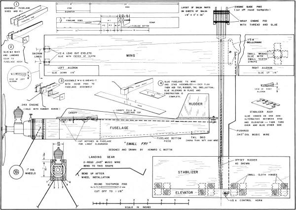
Small Fry Special Plans
<click for larger
version>
Notice:
The AMA Plans Service offers a
full-size version of many of the plans show here at a very reasonable cost. They
will scale the plans any size for you. It is always best to buy printed plans because
my scanner versions often have distortions that can cause parts to fit poorly. Purchasing
plans also help to support the operation of the
Academy of Model Aeronautics - the #1
advocate for model aviation throughout the world. If the AMA no longer has this
plan on file, I will be glad to send you my higher resolution version.
Try my Scale Calculator for
Model Airplane Plans.
Posted 11/13/2012
|