|
Who
doesn't love a classic biplane, especially one with a big radial
engine hanging off the nose? The first plane that usually comes
to mind is the Stearman PT-17.
In fact, if you didn't know better, you might mistake the Pitcarain
Mailwing for a Stearman. Yes, the vertical fin and landing gear
is markedly different, and the Stearman doesn't have the pilot headrest
"bump," but paint a Mailwing yellow and blue, and you might easily
fool a lot of us. This model from the August 1968 edition of AAM,
designed and built by Frank Beatty is for control line. One unique
feature is that the dummy cylinders for the radial engine were constructed
from a plastic
Monogram Wright Cyclone 9-cylinder engine kit. The assembly
drawing and plans are exceptionally well done. The Pitcairn Mailwing
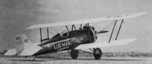
FRANK W. BEATTY Designed for night air mail in 1927 this
plane brought reliability to the Air Mail Service. A control-line
masterpiece for 35 power. The Pitcairn Mailwing was specifically
designed in 1927 to be sold to contract mail carriers for night
air mail runs. An immediate success, this craft which could carry
600 lbs. of mail at speeds up to 136 mph was being produced at the
rate of one per week by the end of 1928. Many an airline that is
world-famous today was equipped with Mailwings during this era.
The model's high-gloss finish reflects prize-winning detail
and workmanship. Lighting can be operative and the engine exhaust
can be routed through the curvaceous manifold.
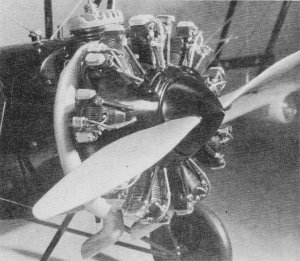
Monogram Wright engine kit was the source of the scale cylinders.
They are mounted on a removable false cowl and are loaded with
lead weight.
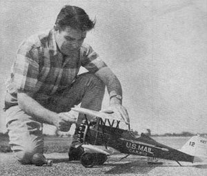
The "anti genius" fires up the McCoy 35 R/C. It is well built
and not a light-weight, and is a realistic flyer.
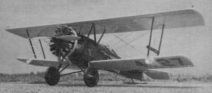
At the field, ready to receive its load
of air mail for the night, our well-detailed Mailwing awaits
action. The cover of the May issue shows a restored mint-condition.
Mailwing at Fredericksburg, Va. Authentic colors and some extra
details were shown.
Many Mailwings finished out their days as crop dusters and a handful
of Mailwings are still flying today. Well preserved examples can
be seen at the Tallmantz and Smithsonian Air Museums. For many aero-philes
watching the TV late movies, the real star of Blaze of Noon is the
Pitcairn Mailwing. James Triggs' fine three-views which
appeared in the January 1959 American Modeler and the Fall 1960
Air Progress were used in preparing the Mailwing working drawings.
Mr. Triggs' drawings did not include coloring data, but replies
to letters sent to Eastern Air Lines, Tallmantz Aviation and the
Smithsonian Institution all verify that the plane was painted as
described in this article. It was noted that if Mr. Triggs' three-views
were to be enlarged four times, the Monogram Wright Cyclone Plastic
Engine Kit would be exactly the right size for this model. The model
has therefore been built to a rather unusual scale of 1 3/16" =
1' and has a 39" wingspan and a 26" length. The ship is powered
by a McCoy 35 R/C engine with a Roberts bellcrank operated throttle
and all up weight is some 51 ounces. It was originally intended
that the Mailwing's construction would follow closely an old favorite
sport scale model built many years ago - Chuck Hollinger's Fleet
Biplane (Air Trails May 1951). Such a model would have gone together
much faster and would have had some stunt capability. But as the
drawings and construction proceeded, more details with their supporting
structures and vast amounts of filler and dope were added until
the model far exceeded its original proposed weight. The Mailwing's
configuration is such that unless some care is exercised in keeping
the model's tail as light as possible, ballast will be required
in the model's nose. Having gone overboard on details and paint,
the Mailwing required some 10 ounces of ballast in its nose; six
to eight of these ounces being packed in the hollow plastic engine
cylinders. Many of my scale models have had wing loadings of 20-25
ounces per hundred square inches of wing area, so this model which
sounds brick-heavy at 51 ounces has a reasonable (for me) wing loading
of 14.3 ounces per hundred square inches of wing area. It has flown
and handled well, even in gusty-wind contest conditions. A model
of 40 ounces or less could be a true week-end sport flyer, so build
to suit your purposes, but DO NOT FLY your model unless balanced
per drawings. Wings: Cut out all ribs,
spars, spar joiners and leading and trailing edges and cement these
frames together. Shape the leading edges and then add all 1/16"
sheet balsa panels and the tip fairing blocks. Epoxy all pre-shaped
spruce strut and rigging blocks in position and then sand both wings
to final shape. Drill the lower wing rear spar for the 1/8" dowel
aileron supports before cutting ailerons separate. This assures
that the aileron will mate perfectly with the wing on final assembly.
Mark all strut and rigging wire locations on the spruce blocks and
drill all strut locations with a 1/16" dia. drill and all rigging
wire locations with a 1/32" dia. drill. Tail surfaces:
Saw the fin and rudder, and the stabilizer and elevators out of
3/16" sheet balsa. If you plan to install full rigging wire details,
cut a 3/16" wide strip off the rear edge of the fin and stabilizer
and cement 3/16" square spruce spars in their place. This harder
wood will resist the sawing action of vibrating rigging wires far
better than the balsa it replaces. For even better results, install
a 1/16" dia. tubing bushing through these spars at each rigging
wire location. Sand these parts to shape and add the Veco control
horn and hinge details to the horizontal tail surfaces.
Fuselage: Cut out the 1/8" sheet fuselage crutch
members and all bulkheads. Lightly score and crack the crutch members
at stations #3 and#8 and cement all bulkheads between these members.
Epoxy the 3/8" x 1/2" maple motor mounts in position (Bulk-heads
#1 and #2). The Roberts bellcrank with lead out wires bolts in next.
It is good practice for every model that one owns that is equipped
with a Roberts operated throttle to idle down or speed up with an
identical trigger movement at the control handle. Otherwise in an
emergency situation when an automatic reflex might save a ship,
confusion and disaster may result. For this reason a Roberts suspended
bellcrank was installed in an upright position in my model. Analyze
your own fleet of models and the throttle throw of the engine you
will use to determine the proper bellcrank for your model. Temporarily
bolt the engine and pin the horizontal tail surfaces in place to
make up the throttle and elevator linkage wires. Make sure these
move without binding before proceeding. Some slight bending of the
bellcrank pushrod horn will probably be required if the suspended
bellcrank is used.
Make
up the cabane and landing gear struts, then bind and epoxy these
into place. Four of the landing gear struts have short bent-over
ends that pass through the bulkheads to help position and prevent
shifting of these struts during installation and on hard landings.
Epoxy the fuel tank with its special modifications into position
next, followed by all stringers and balsa filler blocks. Make up,
finish and install the cockpit floor and all cockpit details. Epoxy
spruce rigging wire locator block to top of Bulkhead #1 and then
plank fuselage top from Bulkhead # 1 to #4. Do not cut cockpit opening
till after all sanding, doping, and rubbing is completed. Bind 1/16"
dia. aluminum tubing rigging wire locator to Bulkhead #1, install
lower wing spar support, then sheet cover fuselage bottom from Bulkhead
# 1 to # 3. Add tailskid detail. Make up cowling block, hollow same,
fit to model and carve to shape. Note that cowling slides forward
to remove leaving an unsightly hole aft of the McCoy cylinder head
which must be filled with a balsa block that is permanently cemented
to Bulkhead #1. Sand the entire fuselage/noseblock assembly to final
shape and cover these parts with silk. Install all cabane strut
and landing gear strut fairings and reinforce these with silk wrappings.
Assembly: Toughest problem for most people
who attempt biplanes is the finish, assembly, alignment sequence.
Our goal with this model is to be able to dope and rub down all
parts separately and then have all these finished parts cement into
pre-drilled holes that automatically align the wings during final
assembly.
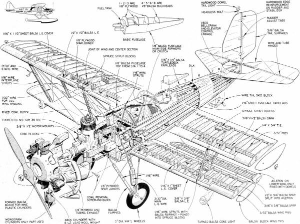
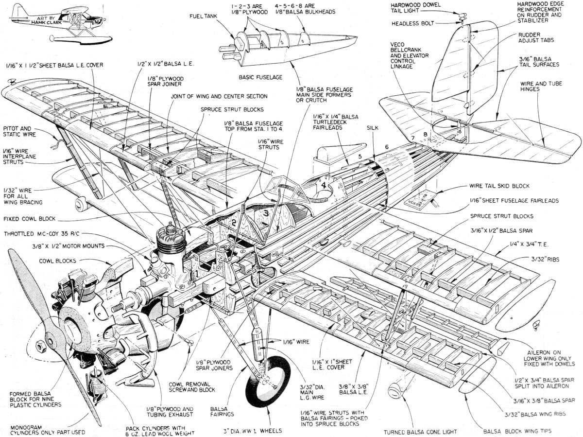
Pitcarain Mailwing Assembly Drawing
<click for larger
version>
Slide the lower wing into position, check for alignment and
cement well. Pin the three balsa wing alignment templates to the
top wing and slide the upper wing into position. Trim just enough
of the balsa cabane strut fairings away so that the center template
rests on the fuselage top when the cabane strut ends have been fed
into the pre-drilled spruce blocks. Bend each 1/16" dia. wire interplane
strut to size and slip into the pre-drilled spruce blocks. After
all interplane struts are fitted, check the assembly for alignment
and pin and tape the whole together rigidly. Solder the brass line
guide to the port pair of interplane struts and then fit all interplane
struts with balsa fairings. It is important for each strut fairing
end to be a close fit. The assembly can now be dismantled and the
struts with their balsa fairings will automatically align the top
wing during future fittings. Set the alignment templates aside,
reassemble and tape the top wing into position again. All the 1/32"
dia. rigging wire can be bent and cut to size and temporarily fitted
in the model. Label each rigging wire with masking tape before dismantling
assembly once more. Soft copper wire can be wrapped and soldered
to each strut or rigging wire end in widely spaced coils. Enlarge
all 1/16" dia. pre-drilled strut location holes to 3/32" dia. and
enlarge all 1/32" dia. rigging wire location holes to 1/16" dia.
A cautious builder might reassemble to check that the fit and overall
alignment of these parts has not changed. Covering:
Cover the wings, struts, and tail surfaces with silk. Make up the
head-rest, landing lights and aileron horn fairings and cement in
position. Prick a pin hole in the fabric at each pre-drilled strut
or rigging wire locator hole or these will be lost under all the
coats of paint to come. Use your favorite method to finish the model.
Briefly, mine consists of four brushed clear coats, followed by
eight thinned-out sprayed filler coats, followed by at least six
thinned sprayed color coats with a wet or dry sanding thrown in
between every two or three coats. Then rub all parts with Aerogloss
Rubbing Compound. Wash thoroughly with soap and water and use home-made
stencils to spray the various marking and lettering details. These
stencils are a story in themselves. Letraset rub-on lettering is
used for the "Pitcairn Mailwing" rudder markings. Protect this rub-on
lettering with a clear dope overspray. Rub these marking and lettering
details with compound. Carefully cut out the cockpit opening and
use white glue to cement very thin leather padding around this opening
and on the headrest. We are now ready for final assembly and detailing.
Butter epoxy cement on all strut ends and slide all cabane
and interplane struts into the appropriate pre-drilled holes in
the top and bottom wings. The wings should be accurately aligned
automatically. Tape this assembly together and allow to dry overnight.
The following day all rigging wire ends can be buttered with epoxy
and slid into position. These too should dry overnight. Cement all
tail surfaces to the model. Make up and finish details like the
windshield, oil and gas filler caps, steps, aileron horns, vibration
dampeners, pitot tubes, position lights and wheels and cement or
solder these to the model. Dummy engine:
The Monogram Wright Cyclone Plastic Engine Kit PE52 was cannibalized
for the cylinder details. The cylinders were filed so that a 1/8"
dia. dowel pin could be centered in the cylinder for alignment and
reinforcing. Before joining the cylinder halves, pack each with
lead wool, About seven ounces of ballast can be packed in the nine
cylinders. Additional ballast can be installed in the cowling bottom.
The author's model required about 10 ounces of ballast for proper
balance for control-line flying. See plans for drawing of a simple
jig that can be bolted to the McCoy crankshaft to drill the 1/8"
dia. pilot holes for the cylinder dowel pins. After all pilot holes
are drilled, carefully cut away cowling at the base of each cylinder
until proper cylinder height is attained. The reverse side of the
afore-mentioned jig will accurately locate the height of each cylinder.
Install the push-rod and ignition harness details with plastic cement.
None of the Pactra enamels or plastic parts used in detailing the
cylinder details seem to have been effected by our model fuels.
Weight can be tolerated in the model's nose, so use plywood and
tubing where desirable for strength when making the exhaust collector
ring detail. Rather than have an unsightly needle valve
extension shaft cluttering up the engine and cowling details, the
entire flexible spring needle valve extension was snipped off. Needle
valve adjustments cannot be made with the cowling in place. Needle
valve adjustments must be made with the cowling removed prior to
moving to the flight circle. When a satisfactory adjustment has
been achieved, the cowling can be replaced and model is ready for
flight. The McCoy does not have a touchy needle valve setting so
this is a safe procedure. This procedure would not be practical
for all model engines. Recommended for those who love classic
biplanes, contest flying, and trophy collecting, the Mailwing is
hard to beat!

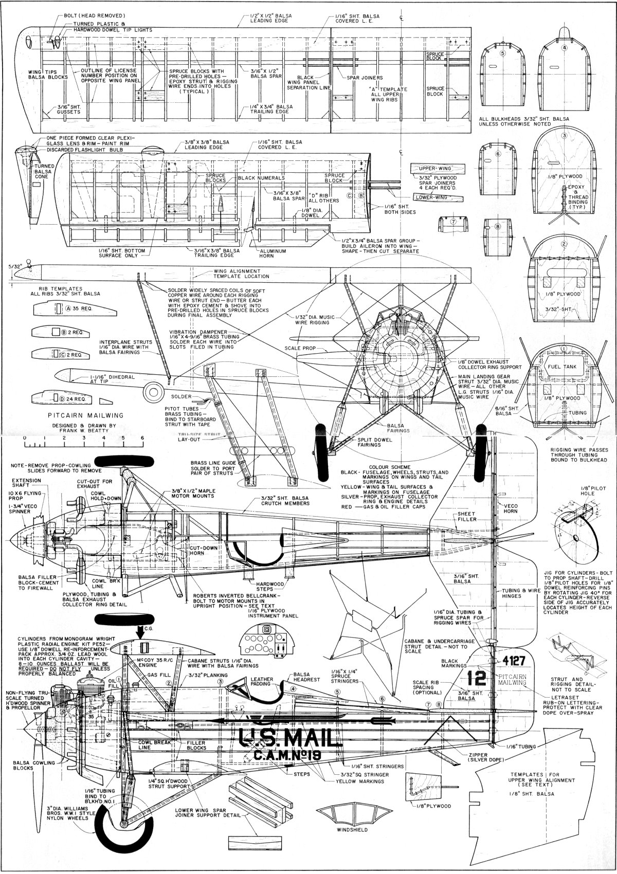
Pitcairin Mailwing Plans
<click for larger
version>
Notice:
The AMA Plans Service offers a
full-size version of many of the plans show here at a very reasonable cost. They
will scale the plans any size for you. It is always best to buy printed plans because
my scanner versions often have distortions that can cause parts to fit poorly. Purchasing
plans also help to support the operation of the
Academy of Model Aeronautics - the #1
advocate for model aviation throughout the world. If the AMA no longer has this
plan on file, I will be glad to send you my higher resolution version.
Try my Scale Calculator for
Model Airplane Plans.
Posted October 16, 2010
|