|
Website visitor Barry G. (of
Australia) wrote to ask to have the article for Claude McCullough's Fletcher FU-24 scanned
and posted. It appeared in the September 1971 edition of American Aircraft modeler. The
Fletcher is an Australian crop duster that looks and flies more like a sport plane than
a crop duster. A unique feature of the FU-24 is its all-flying horizontal stabilizer
(aka stabilator). The plans are high detailed with lots of good fodder for scale trimmings.
There are lot of names credited on the plans. Claude McCullough drew them, with attributions
given to Harld De bolt, Dick Grahm, Bill Hannan, Gerald Barden, and Maj. L.G. (Don) Halls
for contributing scale data.
Interestingly, Mr. McCullough lived in Ottumwa, Iowa, at the time, which is the hometown
of Corporal Walter (Radar) O'Reilly from the M.A.S.H. television show!
Fletcher FU-24
This down-under duster from Australia offers every desirable feature a scale
modeler could ask. Plenty of details can be added, structure is simple, flies like a
trainer.
By Claude McCullough
 Dick Graham first noticed the possibilities of
the Fletcher for RC scale when it appeared in a spark plug ad! To find more data, he
contacted the FU-24 Project Engineer for the Sargent-Fletcher Co., Gerald M. Barden,
who turned out to be a modeler of over 40 years standing and was glad to assist with
the project. Design rights for the aircraft had been sold to Air Parts, Ltd., of New
Zealand, and Barden had spent some time there helping get it into production and test-flying
the first 42 off the line. Dick Graham first noticed the possibilities of
the Fletcher for RC scale when it appeared in a spark plug ad! To find more data, he
contacted the FU-24 Project Engineer for the Sargent-Fletcher Co., Gerald M. Barden,
who turned out to be a modeler of over 40 years standing and was glad to assist with
the project. Design rights for the aircraft had been sold to Air Parts, Ltd., of New
Zealand, and Barden had spent some time there helping get it into production and test-flying
the first 42 off the line.
Only a few drawings were still available in the U.S. and the "General Arrangement"
unfortunately proved to be like many factory drawings of this type - very general, not
really meant to be an accurate outline but more a pictorial representation. It was fine
for some purposes but not for modeling. In this case, the side view did not match with
the top, and Dick became discouraged with the idea of presenting this to a judge as proof
of fidelity.
However, I couldn't get the Fletcher's trike gear, generous area of thick wing, and
functional lines out of my head and mentioned this interest to a kindred scale enthusiast,
Major Langdon Halls. In quick succession, he located FU-24's at Armidale, Australia;
photographed and measured them on a bitterly cold day; drew a set of his superb 3-views
(subsequently published in Australian Modeler); and supplied me with copies. With such
friends, it's no wonder scale is a growing fraternity.
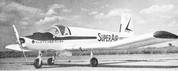
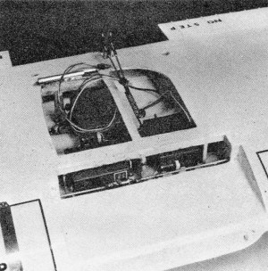
 Real plane is surprisingly large, using a
big 300-hp engine. Even with full load, it gets airborne quickly, works efficiently.
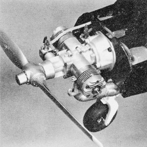
Photo was taken two years ago, but the Bantam Twin engine is just now becoming available.
Note mounting structure.
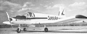
Dusters are not meant for speed, so it all hangs out. Brake line must be easily serviced
in the field. Box could open by radio.
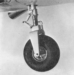
Carefully concealed is a stock Breiten nose gear. Fork built up with balsa, shim stock,
and Epoxolite. Du-Bro wheel fits scale.
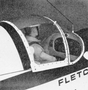
A championship model requires complete interior detailing. Plastic pilot wears hand-made
uniform.
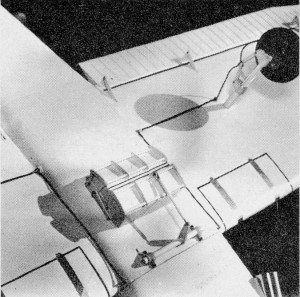
Wide scale fuselages permit several servos to hide in wing. Auxiliary servo for duster
dumping or electric brakes.
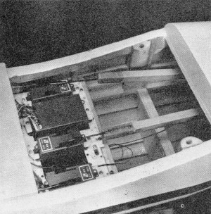
Cockpit floor at left recesses into wing center section. Radio receiver mounts by grommets
to servo mount tray.
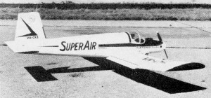
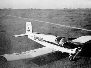
Rear quarter view shows off the simple lines. Flaps down for quick takeoff and steady
slow flight when working.
Since the Bremen World Champs and the first International RC Scale meet were coming up
in a few months, the Fletcher looked like an ideal subject. Its non-complex lines, with
no compound curves, would make for speedy building and planking. To meet. the FAI 11-lb.
limit, I sweat over each piece during construction, but by using restraint with the ply
and epoxy and building with Sig Contest balsa wood, the ship eventually turned out just
under 10 lb.
Its slim nose proved an ideal test bed for Ben Shereshaw's experimental 60 twin-cylinder
engine, now going into production. The Bantam lays to rest old theories that said a twin
wouldn't have good power or idle. It pulls a big model around with ease. As for idle,
at Bremen I hadn't had time to install brakes but was able to come to a complete stop
without them for proto taxi. The Fletcher also made the only touch and go of the meet.
Scale has long needed a twin but this engine also should find plenty of use elsewhere,
since the vibration level won't shake radio equipment apart. Use of a standard 60 in
the model will require extending the head through the cowl, side-mounted or inverted.
The all-moving stabilator of the Fletcher was eyed with a little trepidation, since
some attempts to use these on RC jobs haven't worked out well. However, in this design
the control response proved just about right, without any deviation from scale or resorting
to servo movement reducing gimmicks. Luckily the plane has a deep enough fuselage under
the tail to get in a sufficiently long control horn (make it as long as is possible).
Also keep in mind that an adjustment of the clevis has a much greater effect than in
a conventional stab-elevator setup. After the last test flight at Frankfurt before the
Bremen contest, we applied a little too much correction for a slight nose down tendency
and overdid it, causing some trim problems during official flying. (Some time after the
International meet, it was discovered that the computer goofed and the Fletcher should
have been placed sixth instead of seventh as announced.)
Construction
The only readily available published information on the Fletcher appeared in the May
1962 Flying Magazine. It features a pilot report and history on the aircraft, along with
photos of the utility version which is equipped with windows and seats for passengers.
This would be an interesting modification of the basic model for those who don't want
to get into the functional detail of the duster.
Don Halls has loaned me the negatives of his fine pictures in color and black and
white and I'll undertake supplying copies at cost. Send a self-addressed, stamped envelope
to Claude McCullough, Rural Route 5, Ottumwa, Iowa 52501, for complete information. There
is no substitute for having photos of the prototype for accurate details and this set
of shots shows close-ups of the landing gear, cockpit, cowl, dust box, etc., as well
as views of the complete airplane.
Sig will assist in duplicating the model by providing the big canopy and some small
moldings for lights and scoops. Cost is $3.25 plus 50 cents postage. Mark the item: "Attention:
Maxey Hester."
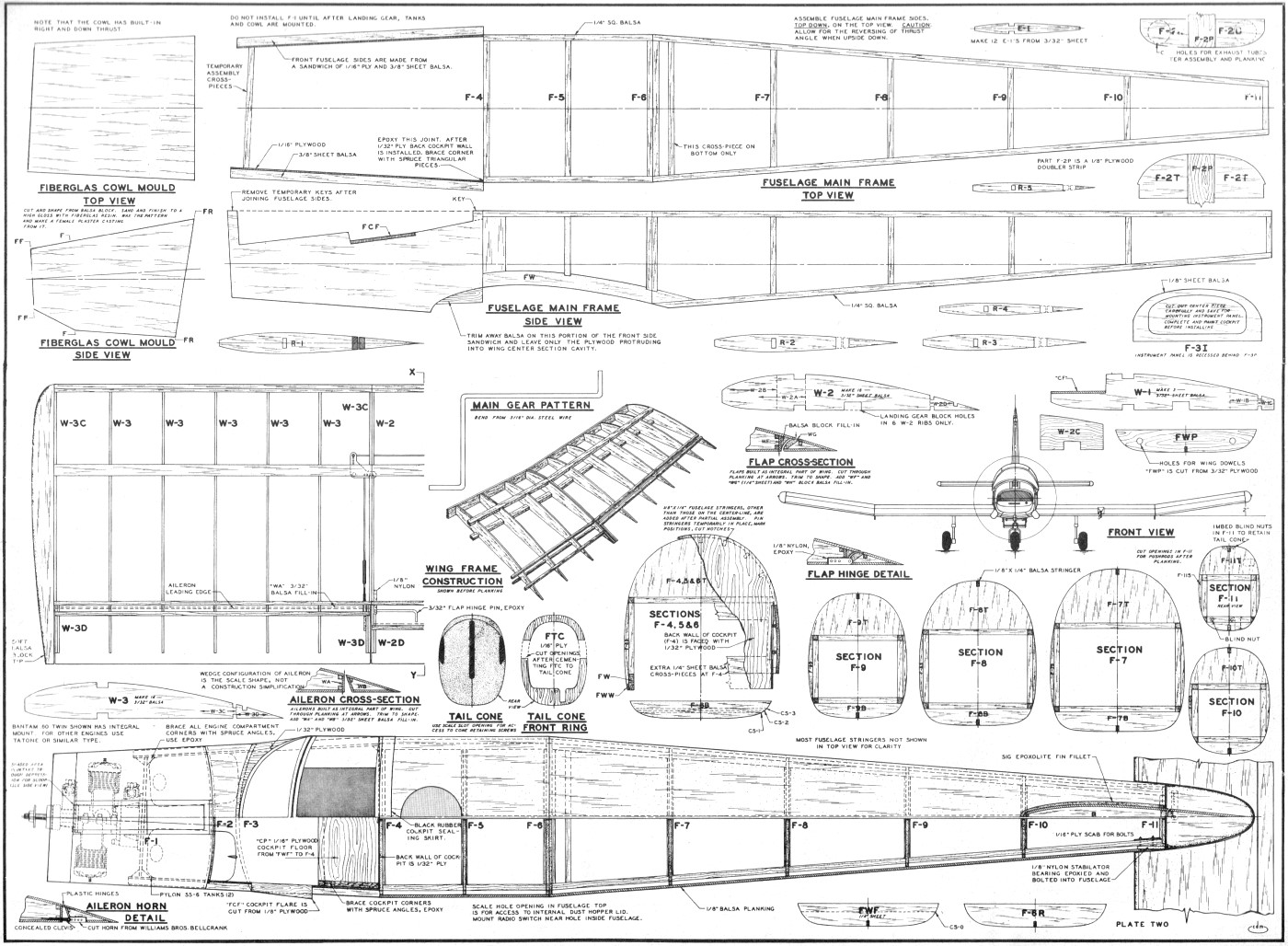
Most of the necessary construction information is on the plan. The only unusual area
is the nose section which requires some ingenuity to get everything shoe-horned in and
still leave some structure. A complete cockpit with reasonably thin walls also must be
accommodated. The design worked out well, as shown, but care must be taken to join solidly
all joints between the ply and balsa sandwich which forms the sides of the nose and the
rest of the fuselage. All the corners in this area should be reinforced with epoxied
spruce angles.
Do not omit the cockpit floor since the channel strength formed by the sides and bottom
is necessary to keep the structural integrity. Note particularly that F-1 is not attached
until after the landing gear, tanks, rear cowl attachment blocks and exhaust augmenter
tubes are installed.
One part of the nose construction not shown on the plans depends on the engine being
used. Where the mounting bolts for the motor or motor mounts go through the firewall
F-1, put a full length 1/8 x 3/8" ply doubler on the rear side. Two pieces of 1/8" ply
are then hand-fitted into the area between F-1 and F-2, one end in the corner formed
by a side of the mounting bolt doublers and the other end epoxied against F-2 in the
area between the tank holes. (See photo of nose with cowling off.) The depth of these
pieces is determined by the available space. With the Bantam, one side was full depth,
the other only partial because the thrust angle puts one tank in the way. The final result
is very strong.
The tanks can be inserted from the cockpit but it is not easy and a few comers may
need tapering and rounding. Since the tanks go in easier than they will come out, do
painting and any other interior work before putting them in. It is seldom necessary to
remove them. A bead of Sig Epoxolite is formed around the tanks on the front of F-2 to
prevent fuel seepage into the cockpit.
To avoid a lot of oil and fuel gook in the engine compartment, use mufflers directed
right into the exhaust augmenter tubes. Since positioning of the mufflers will depend
upon the engine, holes in F-1 to pass them must be custom cut to fit. If mufflers are
not used, some holes in F-1 are still needed to allow cooling air to exit.
The stabilator hinges were made of telescoped brass tubing so that the unit could
be removed for shipment or detached for repair in the event of crash damage. To line
up the two outer tubes for imbedding in Epoxolite, run a piece of dowel between them.
When they set up, saw a piece out of the dowel so it can be removed. Another long straight
dowel should be used between the 1/8" nylon bearings on each side of the fuselage when
mounting them to insure the stabilator will go on square.
A female mold for the fiberglass cowl is cast in plaster, using a pattern which is
made from balsa block, then coated with resin and polished. For casting, build an open-topped
plywood box which is a little bigger than the wooden pattern and may be knocked down
easily. Place the pattern in back side down and fill the box with plaster. When it is
sufficiently set, turn the box over with the bottom side up and pull out the nails holding
it together. This will expose the back of the pattern. Screw a large clothes line hook
into it the balsa and pull out, keeping in mind the taper of the sides requires a slight
angle. Coat the cast with release agent and paint the inside with one coat of resin.
When dry, add another coat. When tacky to the touch, lay in a layer of fine cloth and
give it another coat of resin.
I've ruined too many cowls trying to get them out of deep molds, so I no longer try.
Plaster is cheap and a mold easy to make. Cut into all four sides with a saw nearly to
the cowl and split the mold open with a hammer and chisel. Carefully sand the cowl to
remove the release wax.
The number of stringers used in the fuselage are limited to keep the weight down.
As the covering ages, the planking sinks in a certain amount. The stringers shown in
the plan are used on the model but, for the negligible weight gain involved, the number
could be increased, particularly on the fuselage top. Key stringers could be made from
spruce to insure retaining a more accurate and attractive shape.
In a day of quick coverings and finishes, it is still hard to beat the quality of
a silk and dope application for a scale model. I covered every part with silk and filled
the grain with two heavy coats of Sig Sanding Sealer, sprayed on and sanded between coats.
Spraying prevents brush marks and other uneven spots and gives a perfectly smooth base
for the color dope. It also requires less filler coat because there are fewer ups and
downs to level.
Before the color dope is applied, much of the surface detail (rivets, panel lines,
stiffening crimps, etc.) should be added. Panel lines were scribed into the fillercoat
surface with a replaceable-point scribing tool, using a new, sharp point. For information
on the rivet method, stiffener crimps and other fine detailing techniques, see the RC
Scale section of the "Where the Action Is" in AAM for the past several months, as well
as future columns.
Only two sprayed coats of Sig Supercoat White dope were necessary to cover the white
surface of the Sanding Sealer fillercoat base. Supercoat has a low-shrink base which
helps control warping and planking distortion. Colors of the markings and lettering are
shown on the plan.
Most of the lettering was done with Letraset rub-on dry decals obtainable from art
supply stores. A little practice is necessary to get these on the model without rubbing
so hard as to make an indentation in the wood.
Try them out on an old model. I got good results with a ball point pen as a tool,
using very closely spaced, actually overlapping, strokes and light pressure. Don't be
in a hurry for the letter to separate. Take some additional care with the larger letters
so their shape is not distorted during application. It helps to work from center to ends,
following the letter and not going across open spaces to another part of it. So does
pressing down on the letter firmly with a finger before beginning to rub. Although decal
directions specify using the entire sheet intact, it seemed easier to cut out each letter
with as much border of mounting material as .possible, especially in the larger sizes.
Spray clear dope over the decal letters with great care, using only a haze at first and
allowing each coat to dry until some coverage is built up.
The
following Letraset sheets were used: 26-60CN, fin numerals; 6-96L, "ap" trademark; 26-36CLN,
No Step on gas tank; 26-30CLN, No Step on flaps; 54-36CN, Fletcher FU-24 on nose; 75-42CLN,
Armidale on fuselage. The large wing registration letters were marked on the wing with
a soft pencil from paper patterns, outlined with a ruling pen filled with black dope
and filled in by hand.
Balance point for the model is between 3 1/4 and 3 1/2" back from the leading edge
of the wing. Setting the stabilator angle is too critical a job to be done by eyeball.
Get a big, flat piece of corrugated cardboard and make a template from the side view
of the fuselage. The template can be placed against the flat bottom of the scale NACA
4415 airfoil and provide a cradle back at the tail that will fit the profile of the stabilator
to push it into the correct relationship. Then give the clevis an extra half turn of
up trim for good luck. It's better to have a little too much up than down on a test flight.
I'd be glad to try to answer any questions about construction and would like to see
some photos of other Fletchers.
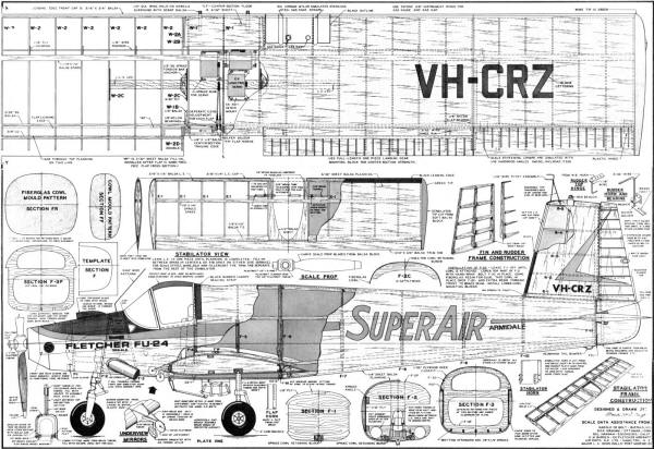
Fletcher FU-24 Plans(sheet 1) <click
for larger version>
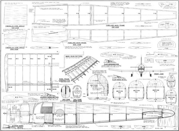 Fletcher FU-24 Plans
(sheet 2) <click for larger version>
Notice:
The AMA Plans Service offers a
full-size version of many of the plans show here at a very reasonable cost. They
will scale the plans any size for you. It is always best to buy printed plans because
my scanner versions often have distortions that can cause parts to fit poorly. Purchasing
plans also help to support the operation of the
Academy of Model Aeronautics - the #1
advocate for model aviation throughout the world. If the AMA no longer has this
plan on file, I will be glad to send you my higher resolution version.
Try my Scale Calculator for
Model Airplane Plans.
Posted August 29, 2012
|