|
Here is a really nicely
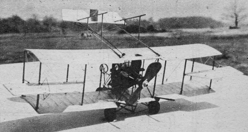
done Curtiss Pusher biplane model for control line. The original model had a 24" wingspan
and was powered by an .049 ignition engine, but you could easily adapt it to electric
power. In fact, doing so would eliminate the hassle of needing to hinge the tail boom
and empennage for accommodations easier engine starting. If you elect to build the Curtiss
Pusher, be prepared to do a lot of work because of the shaped wood sticks for the fuselage,
the undercambered airfoil (which could be modified to flat bottom
airfoil for simplicity in covering), and the flying wire rigging. It does make
a great looking subject, to be sure.
Curtiss Pusher
By Henry Struck
 Back in the days when airplanes were "flying
machines" and jets were gas-light burners, Lincoln Beachey amazed America with his incomparable
precision flying and stunting. He was the first to power dive and zoom, whip stall and
spiral, as well as the first American to fly inverted and loop. To demonstrate the ease
and precision with which he could control his Curtiss "Tripod" pusher, Beachey flew for
miles up and down Chicago boulevards, skimming the tops of autos and trees. Back in the days when airplanes were "flying
machines" and jets were gas-light burners, Lincoln Beachey amazed America with his incomparable
precision flying and stunting. He was the first to power dive and zoom, whip stall and
spiral, as well as the first American to fly inverted and loop. To demonstrate the ease
and precision with which he could control his Curtiss "Tripod" pusher, Beachey flew for
miles up and down Chicago boulevards, skimming the tops of autos and trees.
Lincoln Beachey's machine was the product of the pioneering genius of Glenn Curtiss,
founder of the aircraft enterprises that bear his name today. Curtiss with his talent
for mechanics and zest for speed moved naturally from racing bicycles to motorcycles,
to flying, dominating each field in turn.
Overshadowed perhaps by the more spectacular performances of his flying machines was
Curtiss's development of light weight, reliable power plants - notably the liquid-cooled
Vee arrangement. The engine in Beachey's pusher was the predecessor of the almost universal
OX-5 of the '20's, and today has reached its peak of refinement in the Allison and Rolls
Royce types. This contribution of practical power, enabling others to materialize their
theories of design, hastened the development of the airplane immeasurably.
|

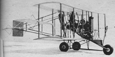
The problem of starting the pusher engine without interference from the boom members
has been solved by hinging the aft section.
|
After Curtiss had taught himself to fly, becoming the holder of international Air
Pilot Certificate No.1, he realized the necessity for training others, and established
the Curtiss Flying Schools. Most of the early pilots, including Beachey, and many World
War I flyers received their early training under this system.
With its premier position in aviation history the Curtiss "Tripod" Pusher is a most
interesting and challenging model project. The numerous flying wires, struts and open
air controls afford the opportunity for much detail.
To support the weight of the Bantam engine successfully the landing gear and center
section braces are an integral structure of piano wire, on which the wings merely rest.
A difficulty: common to all pusher models - flipping the prop for starting - required
a radical solution. The entire tail was hinged at the upper surface and clipped into
sockets at the lower wing, permitting the assembly to be swung up and out of the way
without disconnecting any controls.
In
the absence of a regular fuselage, the wings must be built first to provide a structure
from which the remaining elements of the model may be located. Cut out 52 ribs of 1/16"
sheet, and 6 of 3/8" sheet. This can be greatly speeded up by snipping a wing rib section
from thin sheet metal and cutting around the template with a razor blade. Shape the trailing
edges to a wedge section, 1/32" thick at the rear edge. Pin the leading edge, shaped
of 3/16" x 3/8" hard balsa, to the plan at an angle to match the nose of the ribs. Cement
the tip and center ribs to the leading edge and pin the trailing edge against them. Fit
shims under the junction of the ribs and trailing edges to maintain the contour of the
wing section. Insert the remaining ribs, and fit the spars of 1/16" x 3/16" hard balsa.
Remove the wing from the plan when dry and re-cement all joints. Sandpaper the framework
carefully to remove any bumps that may spoil the finish. Cover the wings with light weight
Silkspan, sticking the paper to the bottom of each rib to preserve the camber of the
section.
Shape the wing struts A, of 1/8" x 3/16" hard balsa to a streamline section at the
center and to 1/8" diam. at the ends. Drill 1/8" holes through the wings and cement the
struts in place, beginning at the tips and working toward the center.
Form the upper portion of the rear motor support B, and the front support D, of 1/16"
piano wire. Cut two plates C, of .020 brass strip. Drill a number of large holes in them
to permit the cement to anchor them securely to the wing surface. Slide the motor supports
through the plates and complete the bends. Push the wire supports through the slots provided
at the center of the wings and cement into the upper wing.
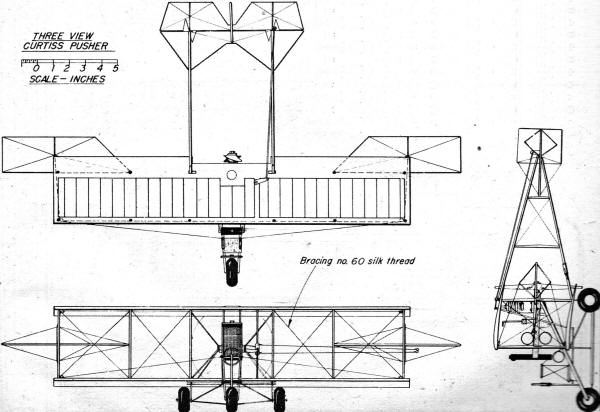
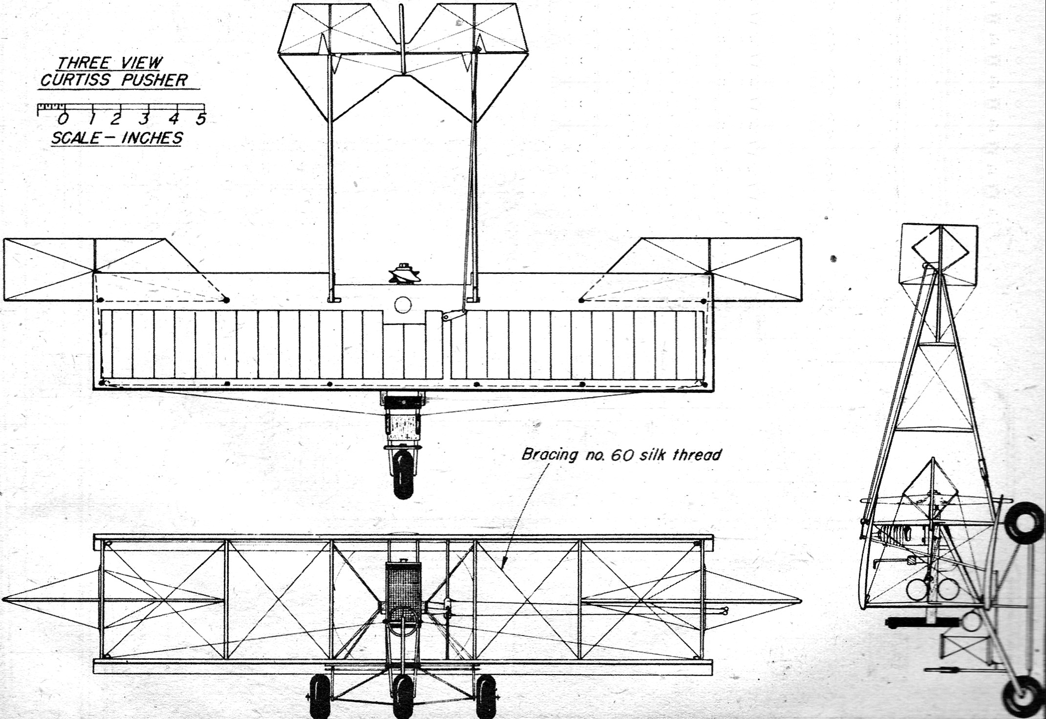
Curtiss Pusher 3-View
Attach the motor mounts E, of ,1/4" x 3/8" maple to the supports with clips F, of
.020 brass strip. Form the motor braces G, of .049 piano wire and work them carefully
into position through the bottom wing. Enlarge the holes through the wing if necessary
to simplify installation. Clamp the braces to the outside of the motor mounts with clips
F. Bend the front wheel support H, of 1/16" piano wire. Clamp the rear end to the inside
of the motor mounts with a brass clip, and bind to the front motor support with fine
wire. Form a pair of rear axle trusses I, of .049 piano wire. Clip the inner ends into
the rear plate C, and bind the outer ends to the motor braces G, with fine wire. Link
the trusses I, to the front wheel support H, with it fork J, of .049 wire, Check the
alignment of the wing assembly carefully - bind all overlapping joints with fine wire,
and solder. Solder the clips F, to the struts, and solder the nuts of the 2-56 machine
screws to the clips to simplify assembly. Solder the struts to the plates C wherever
they pass through. Be sure all parts are clean and bright. Use acid core solder, a well
tinned iron, and the job can be done quickly without danger of charring the wings. Fair
the struts Hand J with strips of 1/8' x 3/16" hard balsa recessed to fit the wire.
Make two bearing plates O, of .020 brass to support the control shaft. Drill 1/8"
holes through the 3/8" thick ribs. Assemble the horn N, of .030 brass and a 1/16" I.D.
eyelet, on the shaft in the mounting bracket M. Solder the horn assembly to the shaft
and slip the unit into the wings. Bolt the bracket to the motor bearers and cement the
bearing plates O in position. Slip the upper horn P, and the lower horn Q on. the shaft
and solder quickly in place to prevent charring the wood. With the horn N parallel to
the motor bearers, the upper horn P should be pointed toward the boom hinge point, at
an angle of about 60°. The lower horn Q points toward the center, parallel to the
wing span.
Fit the engine in place and mark the bolt positions. Remove the bearers and drill.
Attach the motor and work the unit back in place.
Assemble the tail booms directly on the plans of 1/8" dowels, joined by 3/32" x 1/8"
hard balsa streamlined struts. Use several coats of cement at the joints. Lash the hinges
L, to the booms with thread and coat with cement. Slip the booms onto the spur of brace
G protruding above the upper wing. Fit bearing K in place and solder to the wires where
they intersect, using a minimum of solder to prevent seizing up the hinge.
Cut the stabilizer of 3/32" soft sheet balsa, sandpaper carefully and cover with Silkspan.
Set the stabilizer in place and align it with the wings while locating the lower
ends of the booms. Reinforce the boom with a wedge of 1/8" balsa. Cut the lower booms
apart and cement sockets of 1/8" I.D. aluminum tube in place on the stubs. Push the booms
in place and file the notches in the dowel stock. Raise the tail and bevel off the upper
part of the dowel in front of the notch, to permit it to snap into place. Drop the .016
piano wire clip in the notch and lash to the boom with thread and coat with. cement.
Hang the elevator on the stabilizer and solder the horn R, to the left hinge. Form
a 1/8" I.D. eye in a 12" length of .049 piano wire and hook it into horn P. Set the elevator
in neutral, and with horn N parallel to the motor bearers, bend the end of the push rod
into the elevator horn. Solder a small washer to the end of the' wire to retain it in
the horn.
Cut the ailerons of 3/32" soft sheet balsa. On the original model they were hung on
the rear struts with hinges S, of .020 brass. Threads passed over 1/4" diam. eyelets,
cemented in the corners of the front struts, connected the ailerons to the shoulder yoke
at the seat. Diamond shaped horns of .020 wire were cemented to the surfaces. The upper
line was rigged from the left aileron to the right, over the upper fairleads. Each lower
line was rigged to the corresponding side of the shoulder yoke, over the lower fairleads.
For flight the yoke was locked in place. If desired the ailerons may be merely cemented
to the struts, or omitted entirely for flying.
Mount the control column of 3/32" diam. dowel between the seat supports with a short
shaft of .020 wire. Link the column to the U-control system with a push rod of .049 wire.
Cement the control-line guide of .049 wire to the left outboard struts, just below the
ailerons. Attach a pair of .016 lines to horn N, and pass them through the guides.
Install the ignition system using medium size batteries and a midget coil. Solder
all connections and lash the batteries and coil in place with a couple of turns of rubber.
Lead the negative side of the battery to the ground and provide a booster attachment
on the positive side of the coil.
A heavy, wide bladed propeller is necessary to absorb the torque in the small diameter
required. Carve a left hand prop of maple, using a spokeshave and cabinet rasp for speedy
roughing down.
Build up a dummy radiator of 3/8'" soft balsa and cover the front with fine wire screen.
When cemented between the motor bearers the batteries are considerably camouflaged by
it.
Apply several coats of shellac to all bare wood parts. Spray the wings with water
to shrink the tissue and apply two coats of dope, and one of thinned shellac when dry.
Finish all wire struts and horns with flat black paint.
When flying, clip booster leads to the ground and coil. Be sure they are not crossed.
Release the tail booms from the sockets and lay the tail over the top-wing. The prop
can then be easily flipped over in the conventional manner. A length of rubber tubing
slipped over the intake pipe, projecting between the batteries and radiator, may be pinched
shut to simplify choking and eliminate priming. No trouble was encountered in operating
the engine with the propeller specified. Closing the booms while the engine is running
proved even simpler than expected, due to the smooth functioning of the clips. For the
most stable flights the C.G. should be well forward. Add weight to the front wheel support
H, under the seat, if required.
Due to the tricycle landing gear the model may be run easily along the ground, lifted
off when desired and brought down without danger of nosing over while feeling out the
controls.
Wherever exhibited the Curtiss Pusher will always provoke discussion of the pioneer
days, of the men like Lincoln Beachey who flew with such skill and daring, and of others
like Glenn Curtiss who created the machines through vision and infinite patience.
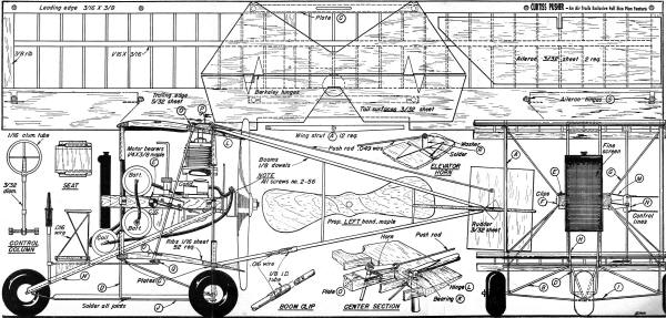
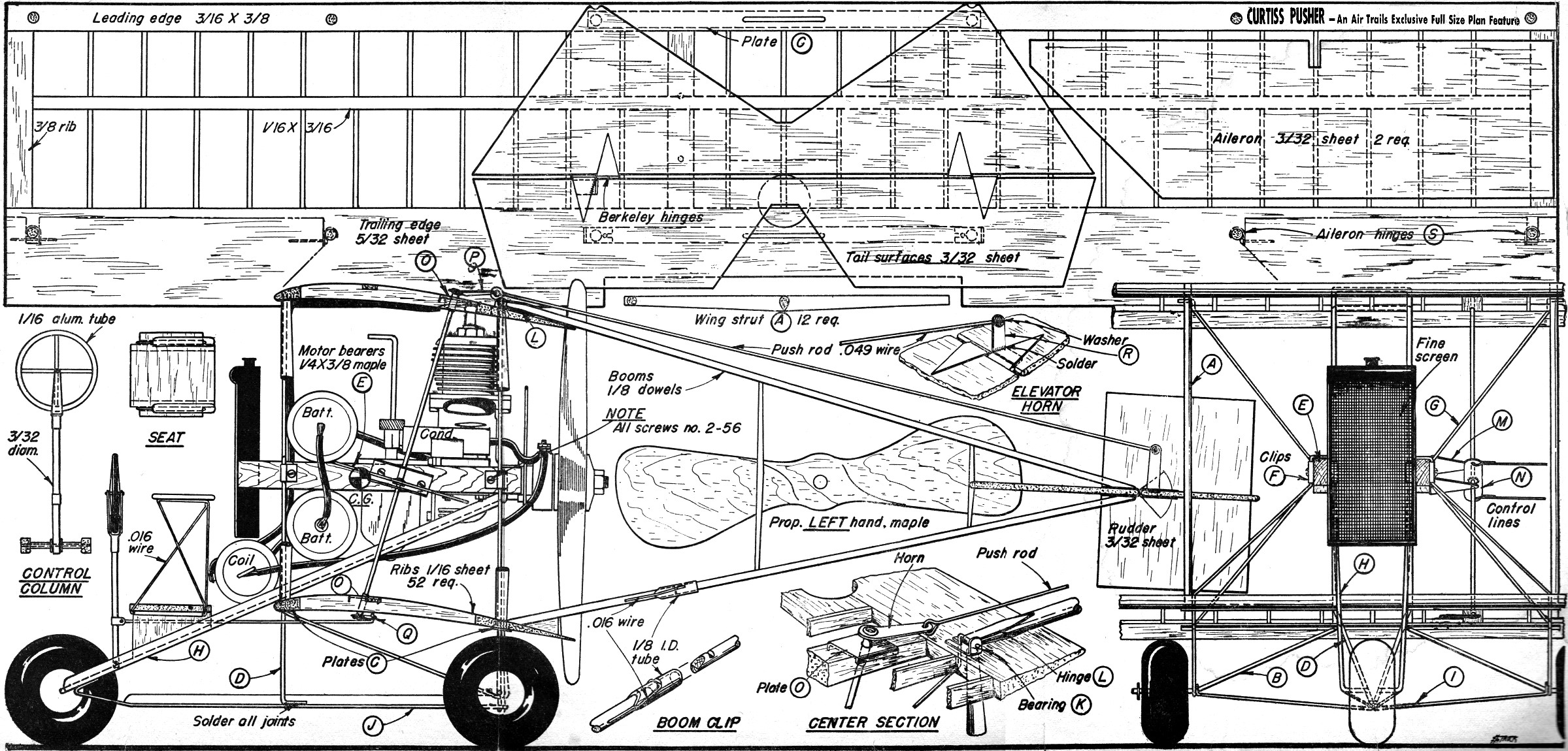
Curtiss Pusher Plans
Notice:
The AMA Plans Service offers a
full-size version of many of the plans show here at a very reasonable cost. They
will scale the plans any size for you. It is always best to buy printed plans because
my scanner versions often have distortions that can cause parts to fit poorly. Purchasing
plans also help to support the operation of the
Academy of Model Aeronautics - the #1
advocate for model aviation throughout the world. If the AMA no longer has this
plan on file, I will be glad to send you my higher resolution version.
Try my Scale Calculator for
Model Airplane Plans.
Posted November 1, 2014
|