|
Walter A. Musciano is a name familiar to most people reading model airplane
magazines anytime from the 1940s through about the 1970s. He was prolific
model designer and artist / draftsman. His detailed drawings of full scale aircraft
are deemed to be amongst the best. This Cub Controller is a 1/2A job sporting a
19" wingspan. It uses both a built-up fuselage and wing, so building requires a
tad more work than the typical profile fuselage and sheet wing often found on models
of this size. The effort pays off, though, in a much nicer looking craft. Mr. Musciano
intended the Cub Controller to be a beginner level project for building and flying,
but having a model or two under your belt prior to this would definitely be an advantage.
If anyone builds a Cub Controller today, he would probably use electric power rather
than the glow fuel Cub .049 or Cox .049 engine. You just can't beat the scream of
an old fashioned 1/2A engine, but the ease of operation and no messy oil to clean
off afterward is definitely nice.
Cub Controller Article & Plans
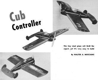 This tiny stunt plane will thrill the expert,
yet it's very easy to build This tiny stunt plane will thrill the expert,
yet it's very easy to build
By Walter A. Musciano
"Easy as ABC" aptly describes the construction and operation of this tiny stunt
plane. Designed around the new easy starting OK Cub glow plug engine, this model
is perfect for the tyro's first attempt at control-line stunt. Yet it will please
the experienced modeler by its performance. With only 90 square inches of wing area
the model can be flown in most any open space. It should not take more than two
evenings to construct this model.
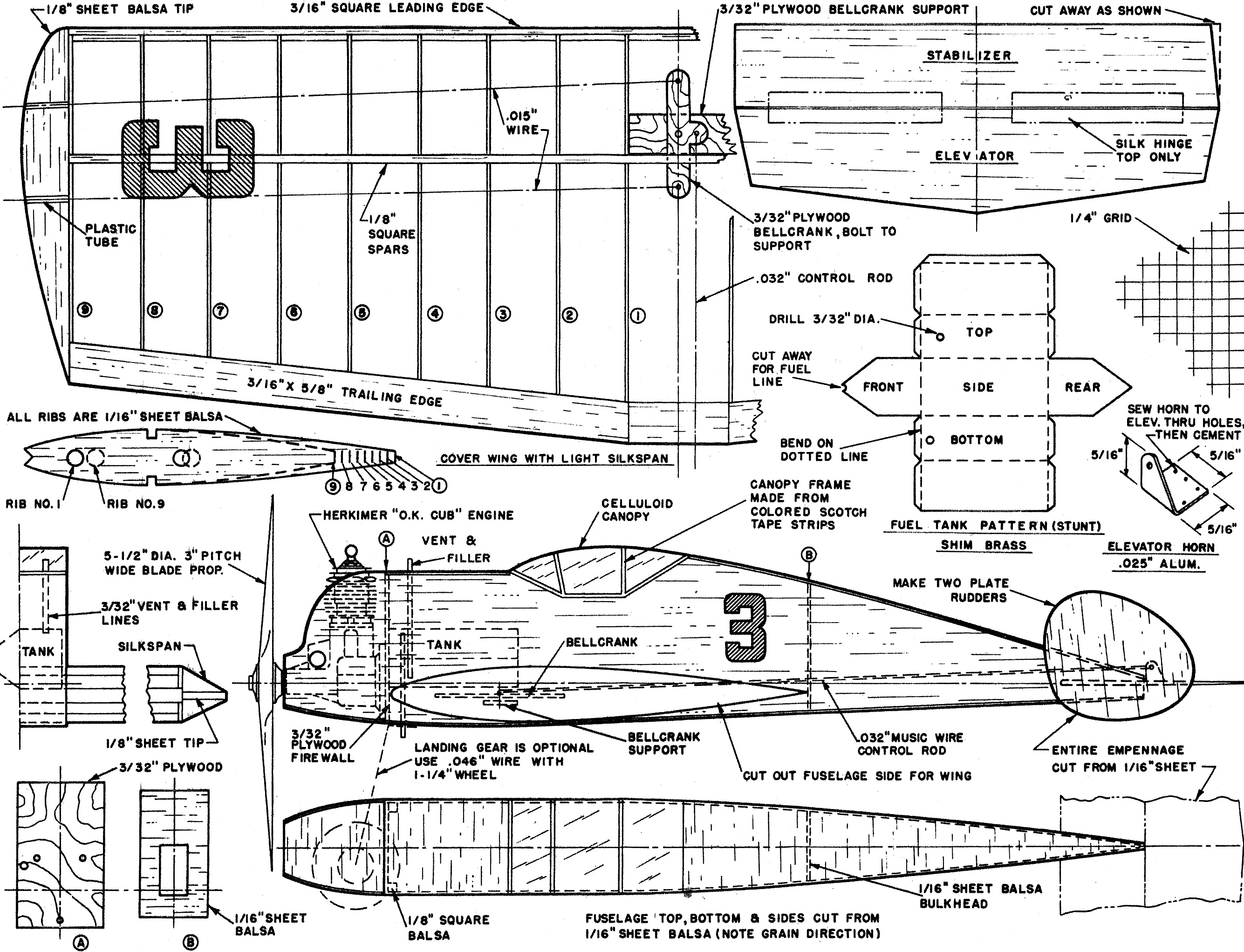
Select medium hard balsa for the fuselage sides and cut these to shape including
the wing and stabilizer slots. Cut out bulkhead B. Cement the rear of fuselage together
and insert bulkhead B. Hold together with straight pins while cement dries. Plywood
firewall A is cut to shape and holes drilled for engine mounting and fuel line.
This should be cemented well to the fuselage. Use 1/8"-square balsa strips to reinforce
this joint. The entire bottom can now be covered from the firewall rearward. The
grain should run spanwise. Cement can be applied through the open fuselage top to
insure an adequate bond.
Cut the tail surfaces from hard 1/16" balsa sheet and sand smooth. When cutting
the stabilizer note that one end is cut at an angle so the plate rudder will be
offset when it is cemented in place. This maintains tension on the flying lines.
The control horn can be cut from dural or metal from a tin can and is sewed and
cemented in place on the elevator. Hinge the elevator and stabilizer with pieces
of fine cloth such as silk. These hinges are cemented to the upper surface only,
but make certain that the elevator moves freely in both up and down positions. Slide
the stabilizer into the fuselage slot and cement well.
The wing is made in one section with no dihedral. This, plus the fact that the
fuselage slot automatically sets the correct incidence angle (which is zero), adds
to the already simple construction. Although the wing is tapered the ribs are easy
to cut and assemble. Medium 1/16" balsa is used for the ribs. These are sanded on
both sides to about 1/20" thickness. All ribs are identical from the spars forward
and the after portions do not vary a great deal from one another. The root and tip
ribs are shown and lengths indicated for those between. Very hard balsa should be
used for the spars and leading edge. The trailing edge is of medium soft balsa.
Mark off the rib locations on the spars and leading and trailing edges. Pin down
the lower spar and cement the ribs in place using pins to hold them upright. Cement
the upper spar followed by the leading and trailing edges.
Cut the plywood bellcrank and bellcrank support. The support is securely cemented
to the root ribs after the 3/32" hole is drilled. The holes in the ribs are easily
made with a leather hole punch or ticket punch. If neither is available holes can
be burned through with a hot three-inch nail. Notice that the leadout wires are
staggered rearward. This helps to keep the lines taut when flying at high angles.
Install the leadout wires and bellcrank at this time. Add the 1/8" sheet wing tips
and when dry, sand the entire structure with fine sandpaper and cover with light
weight Silkspan. Water and dope.
Now slide the wing through the fuselage and cement liberally from inside as well
as outside. When this is dry, cut away the Silkspan in way of bellcrank and install
the control rod.
It is advisable to install the engine at this time. Use small bolts (steel preferred)
and when in place apply several coats of cement over the nuts which should be on
the aft side of the firewall.
The fuel tank pattern is shown on the plan. This type of tank is required only
if stunts are contemplated and is made from very thin shim brass about the thickness
of bond paper. All joints should be well soldered and tested for leaks before the
tank is installed. The tank lays on the wing leading edge and fits between the upper
spar and firewall. Cut away wing covering to install tank. A 1/8" square balsa strip
laid across the top of the tank and cemented to the fuselage sides will hold the
tank in place. The fuel supply line pierces the firewall. In the event that no stunts
are contemplated other than loops, a very .small can will serve as a good gas tank.
Cover the fuselage top from the firewall rearward, and when dry, cover the bottom
forward of the firewall pulling the sides together as the plan view indicates. Sand
the entire model smooth after the engine has been covered with a cloth. The celluloid
canopy is added now. This is made in three pieces. The top is cemented in place
after the two sides have been attached.
The prototype model was hand-launched and landed on its belly. If you desire
a landing gear, cement it to the fuselage bottom now. Use light-weight wheels.
Apply a coat of clear dope to the entire model and one more to the wing. Sand
lightly and apply one coat of thin colored dope for looks. Add decals.
The model was flown on fifteen-foot lines indoors and then on thirty-five-foot
lines outdoors and in both tests the model handled well. Use 0.008"-dia. flying
lines any length you desire up to thirty-five feet. Of course the longer lines are
better for stunting. Before flying be sure that the model balances at the point
where the forward flying line leaves the wing. Addition of lead weight in the nose
or tail will remedy any unbalanced condition. The elimination of landing gear obviously
improves performance. It will be found that the model leaps out of the launcher's
hands. It is suggested that for the first few flights the model be assisted with
a bit of a push until the "art" of launching is understood.

Cub Controller Plans
Notice:
The AMA Plans Service offers a
full-size version of many of the plans show here at a very reasonable cost. They
will scale the plans any size for you. It is always best to buy printed plans because
my scanner versions often have distortions that can cause parts to fit poorly. Purchasing
plans also help to support the operation of the
Academy of Model Aeronautics - the #1
advocate for model aviation throughout the world. If the AMA no longer has this
plan on file, I will be glad to send you my higher resolution version.
Try my Scale Calculator for
Model Airplane Plans.
Posted March 19, 2022
|