|
Website visitor Doug W. wrote
to ask that I scan and post this article on Dave Platt's familiar Contender. It
mentions at the end of the article that Top Flite would soon be kitting the Contender,
which indeed it did. The man down the street from me when I was a kid flew radio
controlled models and he had a Contender (early 1970s). It was covered in yellow
and light blue MonoKote - kind of a strange color scheme. When he crashed it beyond
repair, he gave me the carcass. That was a treasure to me at about 13-14 years old.
It was the closest I had ever come to owning an R/C airplane.
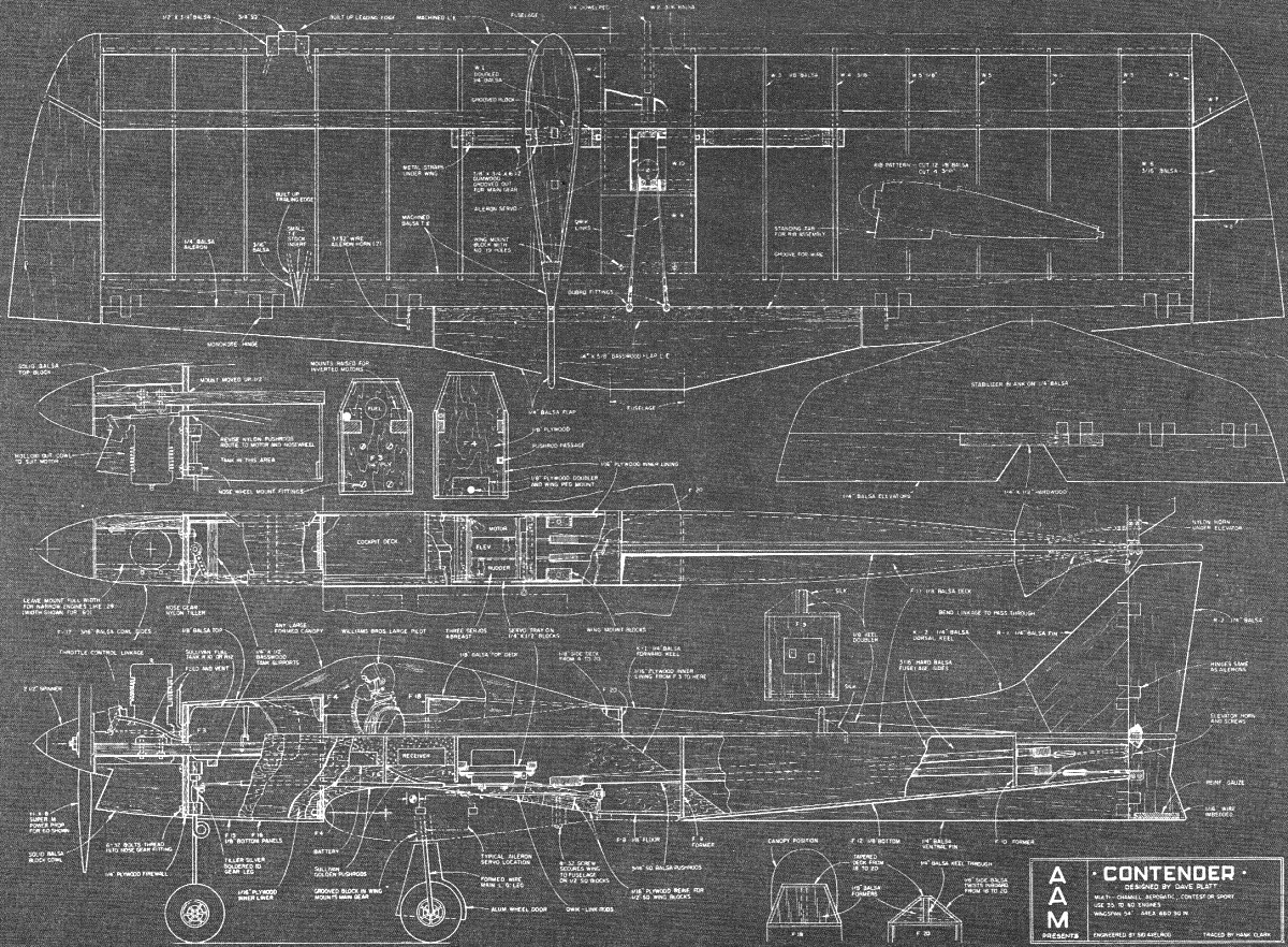
Occasionally, American Aircraft Modeler magazine printed plans in blueprint format, which
is very difficult to use as a model building plan. They definitely do not convert
well to graphical format, even when the image is inverted to turn the lines black
and the background white. Fortunately, AMA Plans Service still offers the plans
for sale. A link is provided at the bottom of the page.
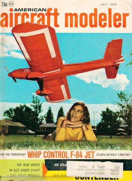
Contender
Contender is a SPORT/STUNT design whose different aerodynamic, structural, and aesthetic
features achieve the goal [of being] easily built from scratch in one week, they
are suitable for novice or expert flyers.
By Dave Platt Photos by Bill Coons
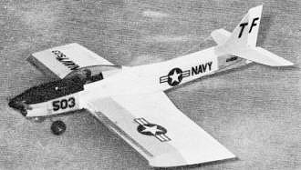
Dave's personal model looks like a fighter with an inverted engine. Airfoil gives
docile handling but large controls make it quite maneuverable for the expert.
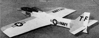
Although scale-like, it uses fewest possible parts and simplest assembly of any
modern RC design. Its design and maneuverability also suitable for CL Stunt.
THE Contender is unusual because it was not intended solely to fill its designer's
needs, as is usually the case, but it was also aimed at the sport flyer and occasional
competitor.
Only one overriding difference exists between today's radio control models and
those of a few years ago. It is not the aerodynamic improvement of design. It is
not the advancements achieved in equipment, engines and, above all, piloting ability,
which have made aerodynamic refinement unnecessary for all except the real pattern
experts. Some new designs are labeled best because of some "latest" aerodynamic
discovery, but any improvement may be due more to faith than to measurable results.
Is it possible that these super-new creations would not be beaten by, say, an Orion
in slightly more expert hands?
What, then, is this big difference? In a word, time. The Orion and its contemporaries
took six to eight weeks, or more, to get ready to fly. Today, even two weeks is
considered too much time spent to reap the reward of a season's flying. Those of
us old enough to remember modeling with cranky engines and crankier radios may feel
a bit wistful about it all. But who wants that kind of trouble again?
The Contender is built quickly because, above all else, that's what it was designed
for. It can be flown by the average pilot as well or better than a model requiring
expert handling for top results. Designed into the Contender are certain helpful
aerodynamic features. Actually, these are not innovations. They are, instead, long-known
but seldom-used methods of creating a stable and predictable airplane. Reasonably
good appearance, but not without sacrificing ease of construction and stability,
was a final design goal. If not radical, at least the Contender looks individual.
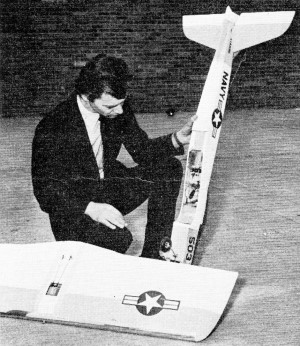
Dave displays innards of his Micro-Avionics-equipped model. He
uses inverted S.T. 60 for power. The plane "explodes into the air."
These three elementary considerations - construction, aerodynamics, and appearance
- dovetailed naturally. For example, it was decided to eliminate dihedral. This
enables the LE, TE, spars, landing gear mount, etc., to be one-piece parts. This
saves much time and improves the strength/weight ratio of the wing. Unfortunately,
a flat wing usually looks drooped, making the model ugly. To retain good appearance,
it was necessary to angle the basic lines of the airplane so that this flat wing
appeared aesthetically suited to the design. The strange shape of the wing, up-front
canopy and unusual length (nearly equal to wing span) have created an optical illusion
akin to a modern swept-wing jet fighter. In these circumstances, a flat wing appears
correct and dihedral would be incongruous.
All other parts were given the severest "do-we-need-it?" tests. All non-vital
pieces were thrown out; vital ones made simpler. The one-piece wing-parts hold the
basic span to under 48 in., although the tips increase this to 54 in. Area is 650
sq. in., so aspect ratio is very low. This makes a compact model which, when assembled,
will fit in most cars.
Aerodynamically, the model incorporates many variations from the norm. There
are no absolutes in model design so one man's approach represents only his opinion.
Mine is that the "drive-the-CG-back-as-far-as-you-can" philosophy is bad for the
average pilot, because it leads to a touchy model with a razor-edged margin of stability.
Instead, I place the CG well forward and achieve the maneuvers by sufficiently large
and far-moving control surfaces to over-power the inherent stability of the model.
This idea works well, because the model does nothing on its own - a clear intent
by the pilot is necessary. This makes for straighter maneuvers which do not require
the expert touch. The ship can now be likened aerodynamically to an arrow in flight,
with a heavy weight forward and tail feathers aft.
This forward CG, coupled with a thick symmetrical section whose camber point
is well forward and radius abnormally large, results in a virtually stall-proof
air-plane. Landing characteristics are delightful. If the model will not stall,
it cannot drop a wing. Normally, a landing is performed by feeding in up-elevator
trim until the ship is gliding on the verge of a stall (just like a contest free-flight
job), then simply leaving the elevator alone and keeping the wings level to the
ground with aileron. The Contender is already in a nose-up attitude, so no flare
is necessary. Ground roll may be five feet or so, or it may not, depending on wind
strength.
Leon Schulman, who made a Contender from original plans, reports that in a gentle
breeze a true stationary hover is easily done by balancing engine rpm and up-elevator
pressure. The seemingly small but highly effective ailerons are adequate to prevent
a sideslip while hovering.
Of course, such reluctance to stall is bought at the expense of something else,
in this case, easy spins. A spin can be done only with a model in a true stalled
condition. The only way to guarantee a clean spin is to give enormous elevator movement,
so the uppermost hole in the elevator horn is used. It might seem that the excessive
elevator control would make the model sensitive near neutral, but this is not the
case. As explained by Ed Kazmirski in his original Taurus article, a large LE radius
gives very soft response close to the neutral.
Contender offers many possibilities for various power situations. The prototypes
used 40's and 60's, but even a 29 would do nicely for those who want to learn to
fly, using this design. On the other hand, a hot 60 gives an altogether different
breed of cat. Add up the formula: weight, 4½ lbs., with thrust, 9½ lbs. Something
is clearly going to happen, and it won't be dull. One of the original Contenders
has a Supertigre G 60 F, powerful enough normally, boosted by installing a Merco
Micro-Flo throttle. This combination has proved outstandingly successful, and more
radio control fans should look at this throttle.
When so powered, the Contender does not take off. It explodes into the air -
the only description which fits. A true 90 degree vertical climb can be maintained
for 500 feet or more, while at 80 degrees it will go up indefinitely. It will climb
in knife-edge flight. It can do square corners of seemingly zero radius. Observers
have been unable to see a curve. On one occasion, 15 consecutive square horizontal
eights were flown, using only the elevator. At the end of all this, the wings were
still level to the ground. No aileron corrections had been necessary - that reliable
forward CG did its work, taking out the expertise usually required for straight
maneuvers.
Bear in mind that, with zero dihedral, a slight yaw will not result in so strong
a rolling force. A degree or so of different heading may result after, say, a square
loop, but it is unnoticeable because there is no bank generated.
Construction is fairly normal. Large LE and TE give the wing its strength. These
parts can be made up easily from three pieces each, if building from the plans.
A standard Kwik-Fli III canopy is used, cut down to fit. It can be tinted to any
desired color in Rit dye (follow directions supplied).
To build the wing, .the standard rib-tab technique is recommended. This will
in-sure a true wing. The engine can be in-stalled upright or inverted. The latter
is preferred, if only for appearance.
The fuselage top is unusual. Instead of using a large block to get the shape,
which is costly and time-consuming, a vertical keel of 1/4-in. sheet is mounted
centered on the 'Is-in. top, then covered straight down to the sides. This results
in a triangular top of crisp appearance. Being balsa-built, the Contender is easily
repaired when the inevitable eventually happens. Who knows?
In time we may even get used to its looks!
Editor's Note: Dave Platt, the author, elected to concentrate his text on the
origins of the Contender, its features, and characteristics. A reader should find
no difficulty in constructing the model without a detailed construction text. The
plans show all the parts in planform and with cutaways illustrate how the parts
go together,
It is helpful to make the wing first. In doing so, assemble and shape the leading
and trailing edge parts first, as illustrated. Cut ribs with the building tabs and
the wing can be made, with no possible warps, on a flat board. The fuselage is built
upside down on the top edge of the fuselage sides, Pre-assemble F4, F3 and the motor
bearers. With these parts properly aligned, install the motor temporarily and epoxy
this assembly together. Then build the rest of the body around it.
Dave Platt offers two practical variations in the fuselage. Hard 3/16-in. balsa
can be used for the sides and the plywood doubler eliminated. He also prefers the
better appearance of an inverted engine installation. See drawing.
Top Flite Models tells us that a kit of the Contender is planned for release
in the summer of 1970, sometime after this article appears. This kit is designed
so that construction, finishing and radio installation can be completed and the
model ready to fly in one week.
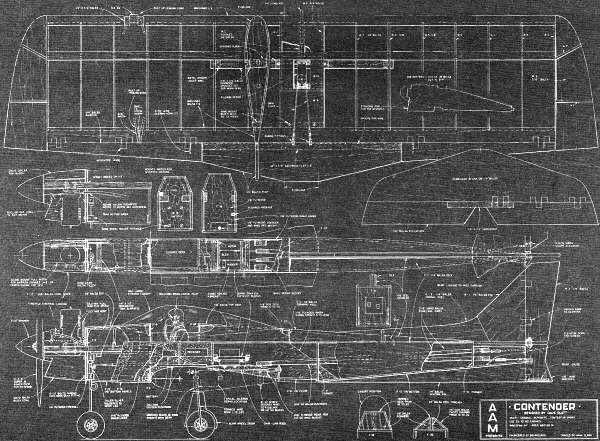
Contender Plans
Note: The inverted color makes even the higher resolution scan
nearly useless.
Notice:
The AMA Plans Service offers a
full-size version of many of the plans show here at a very reasonable cost. They
will scale the plans any size for you. It is always best to buy printed plans because
my scanner versions often have distortions that can cause parts to fit poorly. Purchasing
plans also help to support the operation of the
Academy of Model Aeronautics - the #1
advocate for model aviation throughout the world. If the AMA no longer has this
plan on file, I will be glad to send you my higher resolution version.
Try my Scale Calculator for
Model Airplane Plans.
Posted May 5, 2021
(updated from original post on 4/15/2012)
|