|
The name
Frank Ehling was big in control line circles (pun intended) back in the
middle of the last century. He was a very active modeler in free flight, control
line, and radio control for that matter, and was the Academy of Model
Aeronautics (AMA) technical director for a while. Frank was a prolific and
accomplished airplane designer, plans draftsman, flyer, and competitor. This
article and plans for his "Combat King" control line combat model appeared in
the June 1959 issue of American Modeler magazine. It is a flying wing
design with a 37" wingspan and is meant to powered with a .29 to .35 size
engine. As with most of the vintage model designs, it would easily be converted
to electric power and be competitive. Construction materials are standard
balsa and plywood.
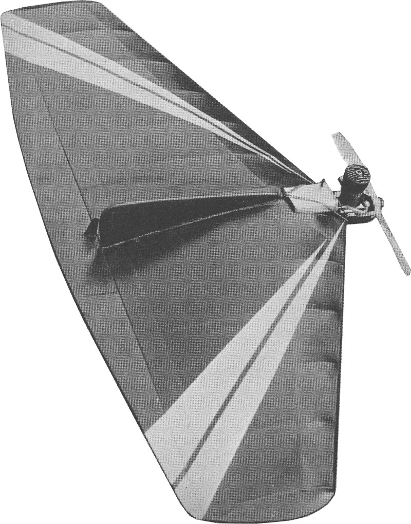
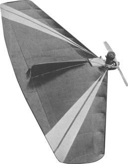
Combat King
 By Frank Ehling By Frank Ehling
Successful combat models must be light, fast, and easy to build. They must "groove"
with ease, yet be easily diverted into a violent evasive maneuver with split-second
response. "Combat King" is the result of several tries at several different types.
For those who argue against "flying planks" - be forewarned - this design, with
a hot Torp 35 up front, will leave nothing to be desired (provided that it is in
capable hands).
If you contemplate making a "Combat King," please keep it light and leave the
design and C.G. as shown - it represents the combined efforts of Bill Harris and
myself. We'll not be responsible for any spur-of-the-moment "improvements" - the
job does fine as is.
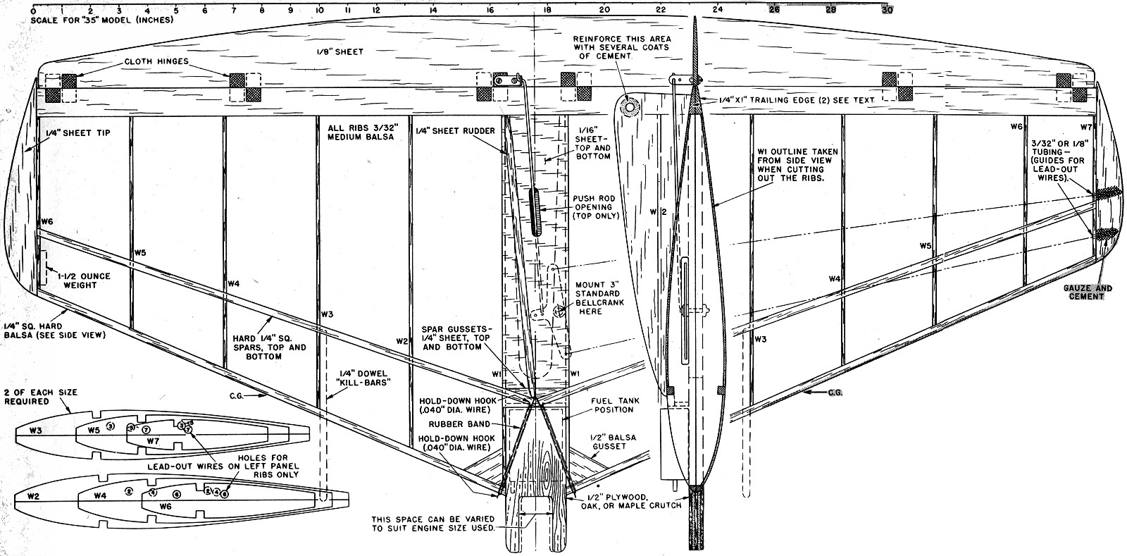
The hardwood crutch is the "heart" of this model and should be cut out first.
1/2" plywood is a good substitute, as strength is the prime consideration. Drill
all necessary holes - if blind nuts are used for mounting the engine, set them in
place and draw them in snug. "Safety" them in place with a heavy coat of cement.
The ribs are cut out - note that they are in halves. This makes for an easy assembling
job. The top section is assembled on a flat surface, allowed to "set" and dry well,
after which it is removed from the workbench. The remaining halves of the ribs go
on, followed by the spar strips and the "doubled" leading and trailing edges (see
cross section on plan). The center section ribs are spaced to suit the particular
engine used - the plans show the proper size for a Torp "35," although most other
29 & 35 engines will have almost exactly the same crankcase dimensions.
The bellcrank is bolted on to the crutch and the crutch in turn is cemented into
place in the center section of the wing. The cutout in the crutch is important -
weight towards the rear is not desired. Fit the elevators, using standard fabric
hinges. The push rod is cut to size, bent and fitted in also. The top center section
is sheeted in (grain spanwise).
Cut the rudder to the outline shown, sand top edges as per plan view and cut
a hole for streamer attachment as shown. Note that this area is coated with cement
to stand the drag of the streamer (plus the tug that sometimes is experienced when
your opponent cuts across your streamer with his wing tip). Note rudder offset,
as the engine is mounted dead straight. Do not reduce rudder offset, as it is very
necessary for line tension. A 1 1/2 ounce weight is secured to the outboard wing
tip at the spot shown. And not half-heartedly, as engine vibration may work it loose,
necessitating wing recovering and doping. Once you have added cement to the underside
of the bellcrank nut (and bolt) you can cover the bottom of the center section with
1/16" sheet like the top.
The "kill-bars" are used to keep your opponents streamer from slipping endwise
off the wing, since it has sweep-back on the leading edge. If they are used, cover
the top wing surface, force the kill-bars through the covering and cement inside
before adding the under-side covering. Silkspan covering is recommended on an "expendable"
model of this type. We used butyrate dope on our Silkspan covering, with dye added
to the dope. This is the lightest way to obtain a color scheme. Use any dye that
is alcohol-soluble. A few coats of clear dope go on first (thinned to whatever consistency
you like), followed by the dye, applied with cotton swabs. A coat of clear over
the dye will keep the color on.
Now you want to get in some flight time - go right ahead, you want to practice
plenty before taking on all comers. At the risk of sounding grumpy, we'll again
repeat that the center of gravity (C.G.) is not to be fiddled with. You'll find
a 10-6 prop just right, if the model fits the 14 to 18 ounce bracket that seems
best. Built right, your Combat King should have no silly quirks or tricks.
The full size ribs given in the magazine are for a 1/2A version - the local boys
find these a "real deal," especially with something like a Holland "Hornet" up front
(the new ones with the built-in restricters). Details are given for the 1/2A job
- a :1/2" wide streamer is used, half the usual "35" length. Using 35 - foot lines,
these little jobs put up quite a showing. Don't forget that about 3 degrees out-thrust
are needed on the 1/2A version to help maintain line tension (this in addition to
rudder offset). A half-ounce weight in the outboard wing tip in the position shown
is a necessary item also.

Combat King Control Line Plans
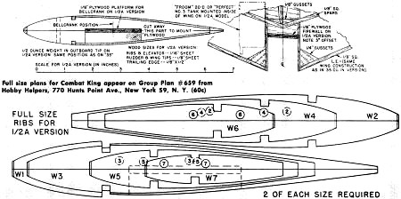
Combat King Control Line Wing Ribs
Notice:
The AMA Plans Service offers a
full-size version of many of the plans show here at a very reasonable cost. They
will scale the plans any size for you. It is always best to buy printed plans because
my scanner versions often have distortions that can cause parts to fit poorly. Purchasing
plans also help to support the operation of the
Academy of Model Aeronautics - the #1
advocate for model aviation throughout the world. If the AMA no longer has this
plan on file, I will be glad to send you my higher resolution version.
Try my Scale Calculator for
Model Airplane Plans.
Posted May 2, 2020
|