|
Website visitor Andrea V., of Italy,
wrote to request that I post this construction article for the Bushmaster R/C airplane.
What makes this model article unique is that it was published in October of 1974 - nearly
40 years ago when electric power was still the realm of relatively few experimenters.
Brushed motors and NiCad batteries were the technology of the day. Adding to the motor
and battery weight is a rather bulky, yet robust airframe with a 61.5" wingspan. The
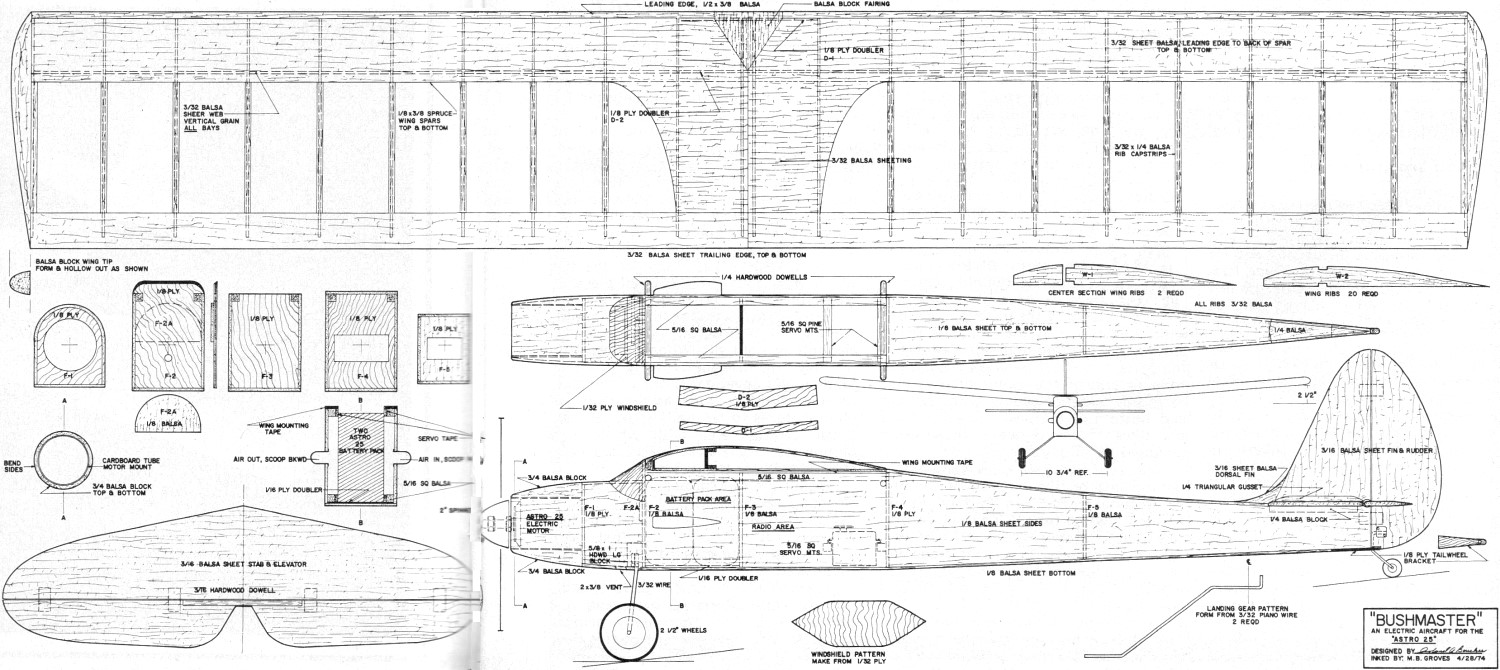
plans in the magazine spanned across two pages and did not stitch together well in the
image below. The AMA does still sell the full-size
Bushmaster plans
if you are interested in building a Bushmaster for the sake of nostalgia.
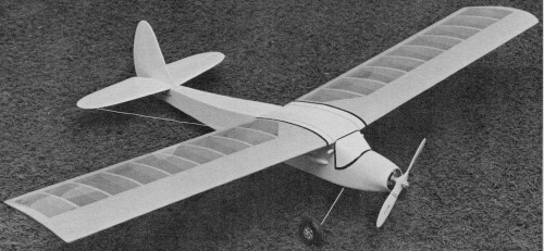
Bushmaster
The Bushmaster captures an "old-timer" flavor, yet uses the most modern power system
available.
by Roland Boucher
Richie Hallerberg, age 12, constructed the first Bushmaster electric-powered, remote-controlled
airplane, and it was successfully flown in February, 1974. Richie scratch-built the airplane
from Astro Flight's preproduction blueprint. The performance of the airplane was outstanding,
yielding fifteen-minute flights continuously. The Bushmaster was Richie's first airplane
and was constructed by him without any assistance.
When setting out to build the Bushmaster, I wanted a simple, easy-to-build plane.
It had to have high-wing stability and light weight, for snappy performance with the
Astro 25 electric power unit. An easy flier was important, because the only time I get
to fly anymore is when giving demonstrations.
I really knew that we had a winner when a twelve-year-old, Richie Hallerberg, built
one as his first model. He came by the shop with his father to buy an Astro 25 for a
projected four-channel airplane. I tried to convince him that three channels were plenty
for a beginner. To demonstrate my point, I took him and his dad to a vacant lot and demonstrated
rudder rolls with an Astro 05-powered VOLTSplane (designed by Henry Pasquet).
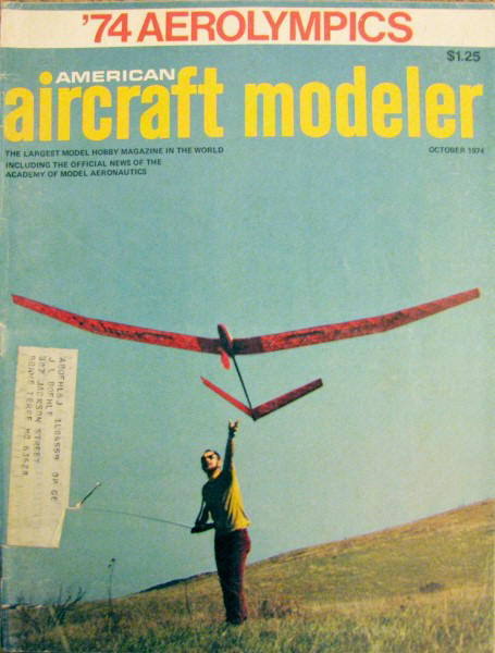
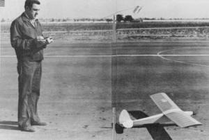 Roland Boucher is shown here out for one
of his infrequent relaxation sessions (no frayed nerves with those quiet electrics).
The Bushmaster is designed to be stable enough for hands which are inclined to become
a little bit rusty at the sticks.
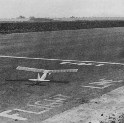
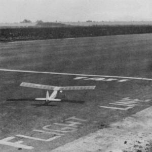 The tail already up, the Bushmaster steps
out. It will be airborne before it's out of the frame of this photo.
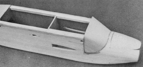
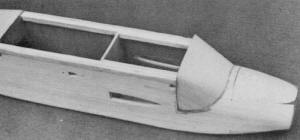 Quick construction is achieved by using large
pieces of balsa, not lots of little sticks. Note the cooling louver for the battery cut
into the side of the fuselage.
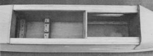 The cabin area is divided into two compartments.
The airborne radio goes to the rear, while the flight pack for the Astro 25 is up front.
I let Richie take the stick for a couple of flights, then went back to the plant to get
a set of Bushmaster plans. Two weeks later, I was pleasantly surprised to receive a call
from Richie's dad. The Bushmaster was ready to fly, and he wanted me to make the maiden
voyage.
An hour later, they arrived. We went out to the vacant lot and found a smooth stretch
of dirt from which to take off. The bird flew every bit as well as my own. Richie flew
a good part of the three flights, getting more proficient each time. He has soloed now,
and is thoroughly enjoying the quiet revolution. He reports that he's getting consistent
15-minute flights.
The Bushmaster's flight capabilities are commendable. The takeoff roll is short, and
climb out to a pattern altitude of 200 feet takes about 20 seconds. Use neutral trim
in the climb, since the high-wing cabin configuration results in a positive nose-up trim
when power is applied. Like most electrics, it is best to climb at a good solid flying
speed rather than to hang on the prop.
Climb to between 50 and 100 feet above pattern altitude. Then crank in 1/4 forward
trim and gently dive back to pattern altitude to "get on the step." Now you are ready
for loops, rolls, wing overs, etc. Snap rolls and spins are also possible if large control
deflections are used (Flying Roland's prototype, I could get three simultaneous snaps
from level flight-not bad!-php.). Recovery from a spin is immediate when controls are
neutralized.
The Bushmaster has a solid feel in the air and, at moderate control deflections, makes
an excellent trainer. It can be flown power-off quite slowly with full back trim, and
has been thermal led in strong lift. For landing, set up your approach, power off, at
full back trim, and flare just before touchdown. Once it's down, it stays there, with
no tendency to bounce. The steerable tail wheel provides positive control on rollout.
The Bushmaster has been a fun project, which was an immediate success on its first flight.
It is easy to build, yet the rounded tail surfaces and large cabin give it a pleasant
"old timer" look reminiscent of Canadian Bush planes. I hope you enjoy building and flying
the Bushmaster as much as I have.
Construction
The Wing: Begin the wing construction by taping the plan to a flat board which should
measure at least 3/4 x 12 x 36". Remember, your completed wing will only be as straight
as your building board! If you use a 62" building board, you can build both wing panels
simultaneously. Now, cover the plan with a piece of saran wrap or similar product. Do
not use waxed paper.
Carefully select your wing sheeting, making sure to match them as closely as possible,
and pin directly on the plan in the correct position. Next, glue the 1/8 x 3/8 x 36"
spruce spar to the top aft edge of the bottom sheeting.
Select a piece of 3/8 x 1/2" stock to be used as a leading edge and glue to the top
forward edge of the bottom wing sheeting.
Cut the wing center section planking from 3/32 x 3 x 36" stock. Then glue and pin
the 3/32 x 1 x 36" trailing edge stock into position on the plan, and glue the bottom
cap strips in place. Cut out all balsa ribs and glue in place (be sure to tilt the first
rib to the correct dihedral angle).
When this is complete, add the top 1/8 x 3/8 x 36" spruce span and glue the 3/32"
sheet shear webs in place between all ribs, except the first pair.
When both wings have been completed to this stage, remove them from the building board,
and trim spars and leading edge to the correct dihedral angle. Pin one wing down on the
building board and join the two wing panels at the correct dihedral angle, using five-minute
epoxy. Also using five-minute epoxy, join the plywood dihedral braces at both the leading
edge and spar joints. The wings are now ready for top sheeting.
Using a straightedge, trim top planking to the proper width, coat the ribs, spar tops
and rear edge of the leading edge with a liberal amount of glue, then lay the top planking
on the wing and pin securely along the leading edge. Next, starting in the middle of
the wing, bend the planking down to the spar and, working toward the wing root, use clothes
pins every inch or so to insure good contact with the spar. Now, work from the middle
to the tip, clamping the sheet securely to the spar.
Next, add the 3/32" top center sheeting, cap strips, and trailing edge. When completed,
leave the wing assembly pinned to the building board overnight to insure that all glue
is completely dry.
When dry, remove the wing from the building board and, pinning the other wing half
down, complete the wing assembly. Let dry, then remove the wing from the board and sand
the leading edge to the approximate shape shown on the plan. Next, attach the wing tips
and sand to shape. When this is complete, sand the wing with progressively finer sandpaper
until all surfaces are very smooth. The wing is now ready for covering.
Tail Section: The tail surfaces are a simple all-sheet design and need only be sanded
to approximate airfoil shape. Be sure to leave the elevator in one piece, gluing the
torsion bar in place and slitting both elevator and horizontal stabilizer for nylon hinges.
Assemble the stabilizer and elevator, and make certain that the elevator moves freely.
When properly aligned, epoxy the hinges in place. Cut the elevators free and sand smooth.
Repeat the above process for the rudder and vertical stabilizer assembly.
Fuselage: After cutting out the fuselage sides, mark the inside of each with the bulkhead
locations. Trim the aft end of each side and glue formers F2 and F4 to the right fuselage
side using five-minute epoxy. When dry, glue the left side to this assembly, making sure
to keep the fuselage square and true.
When dry, pin the fuselage assembly to the plan top-view and pull the rear fuselage
sides together and glue. Hold this together with a clothespin, and install formers F1,
F3 and F5. Be sure to keep the fuselage straight and aligned with the plan. Add the 5/16"
square top longeron between F2 and F4 to keep the fuselage center section straight. Cut
and glue the top rear 3/32" cross grain planking in place now, to ensure that the aft
fuselage is straight.
Roll a motor tube (using 1/32" plywood) by making two turns directly around the Astro-25
motor to insure a snug fit. When dry, install the motor tube into F1 with five-minute
epoxy, being sure to align it straight in the fuselage. Use a spirit level to align with
the building board in order to set the thrust line at 0° incidence.
Remove the fuselage from the building board and install the bottom planking from F2
to the tail.
Cut the balsa doubler which attaches to the forward side of F2 and glue in place with
five-minute epoxy. When dry, wet the outside of the fuselage sides from F2 to the nose.
Slit them at the top, down to the bottom edge of the balsa doubler and bend them around
the motor tube, F 1, and along the balsa doubler (hold in place with masking tape until
dry).
Now, remove the masking tape and carefully fit the sides to F1 and the doubler. Glue
in place, using a piece of scrap balsa to fill the triangular gap which is formed as
the sides are fitted around F1 and the doubler. Next, trim the balsa side sheet between
F1 and the forward end of the motor tube so that each side extends evenly with the top
and bottom of the plywood tube. Glue the sides to the plywood tube, using five-minute
epoxy.
Next, fit two 3/4" thick balsa blocks on top and on the bottom of the plywood tube,
from F1 to the forward end of the plywood tube. Glue in place with five-minute epoxy.
When dry, trim to a smooth contour with a razor plane and sanding block. Cut out the
windshield pattern from 1/32" plywood, fit and glue in place.
Install the landing gear block, the 1/4" square bottom fuselage stringers, the bottom
sheeting between F1 and F2, the plywood battery floor, the 3/32" vertical grain doubler
in the cabin area and, finally, the 3/16" bottom stringer in the battery compartment.
Also, cut holes in the fuselage sides for the battery air scoops. Cut the motor air exit
in the bottom sheeting between F1 and F2.
Cut two servo mounting rails to length, notch for the servos to be used, and install
in the aft cabin compartment. Make up the push rods using the plan side-view as a guide.
Make an exit slot in the fuselage sides for the pushrods and check that they work freely
and without binding.
Install the brass tube for the tail wheel with epoxy and a small piece of glass
cloth.
Trim the notch for the horizontal tail and fit the elevator, checking for any left
or right tilt. When the elevator fits flat, the fuselage is ready for final sanding and
covering. If one of the plastic film finishes, such as Solarfilm or MonoKote, is to be
used, apply it now. Cover canopy area with white trim MonoKote. Trim with black if a
light color is used for the fuselage.
Install the tail surfaces, landing gear, air scoops, and install your Astro-25 and
radio. Your Bushmaster is ready to fly. We wish you luck with your first sport pattern
ship designed especially for electric power.
I would like to thank Dave Shadel, Kenney Wolf, Monte Groves, and my brother, Bob,
for their many helpful suggestions in development of this new aircraft.
 Bushmaster
Plans <click for larger version>
Notice:
The AMA Plans Service offers a
full-size version of many of the plans show here at a very reasonable cost. They
will scale the plans any size for you. It is always best to buy printed plans because
my scanner versions often have distortions that can cause parts to fit poorly. Purchasing
plans also help to support the operation of the
Academy of Model Aeronautics - the #1
advocate for model aviation throughout the world. If the AMA no longer has this
plan on file, I will be glad to send you my higher resolution version.
Try my Scale Calculator for
Model Airplane Plans.
Posted March 17, 2013
|