|
Website visitor Robert C.
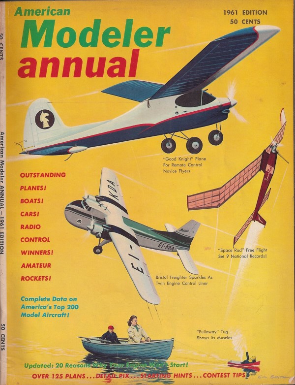
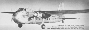
wrote to request that I post the article and plans for the British Bristol "170"
Freighter that appeared in the 1961 Annual edition of American Modeler
magazine. This control line version has a 40" wingspan and is powered by a pair
of .049s for scale-like flight characteristics or a pair .09s if you want aerobatics.
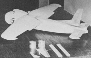
Diesels are shown installed in the original. The fuselage, wing, and tails surfaces
are all built-up and sheeted with balsa, so she is a sturdy bird. As with most of
these vintage models that used glow engines, conversion to electric can be easily
made, and lightening of the structure can be safely done since motors do not create
the extreme vibration loads of internal combustion engines. For instance, the balsa
sheeting of the entire wing could be reduced to only the root area at the fuselage,
and then maybe add a stringer or two along the leading edge top area.
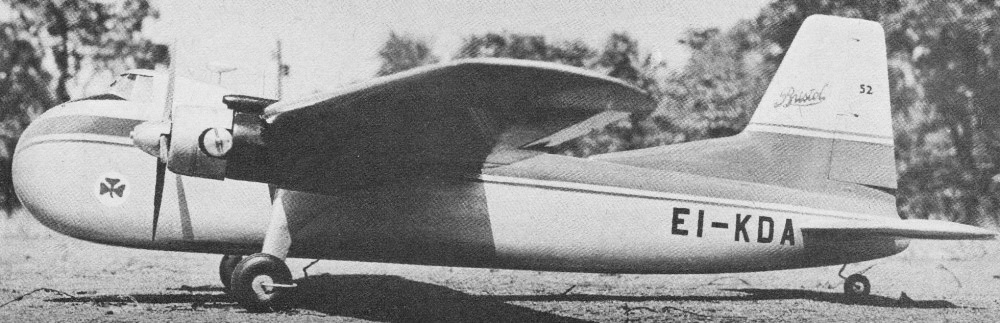
Bristol "170" Freighter
Absolutely Irresistible!
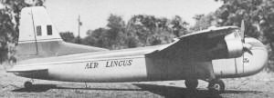
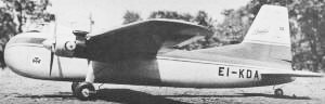
Britain's Bristol 170, a freight-and-passenger version of the Bristol Bombay
bomber-transport, made its first flight in 1945. The 1954 version shown here, little
altered from the earliest type, has seen service all over the world, building up
a record for reliability and economy. No glamour girl, the 170 is a flying machine
par excellence, and our 40 inch version handles just like the big one.
The straightforward engineering of the prototype is reflected in the easy construction
of the model. The fixed gear offers an opportunity to build true scale without the
necessity to fudge details of a retracting gear, and the constant-section elevator,
low-slung circular nacelles and small window area are simpler to construct than
most scale jobs. Powered by two .049's, the 170 performs smoothly on 40 foot lines;
with a couple of .09's up front, you'll have to keep your head or you'll find yourself
looping the dignified old lady.
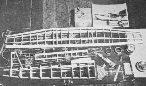
Construction of the 170 is all balsa, with the exception of a little wire and
plywood; no difficult techniques are employed. The secret of turning out a beautiful
job is to work slowly and carefully - and don't spare the sandpaper!
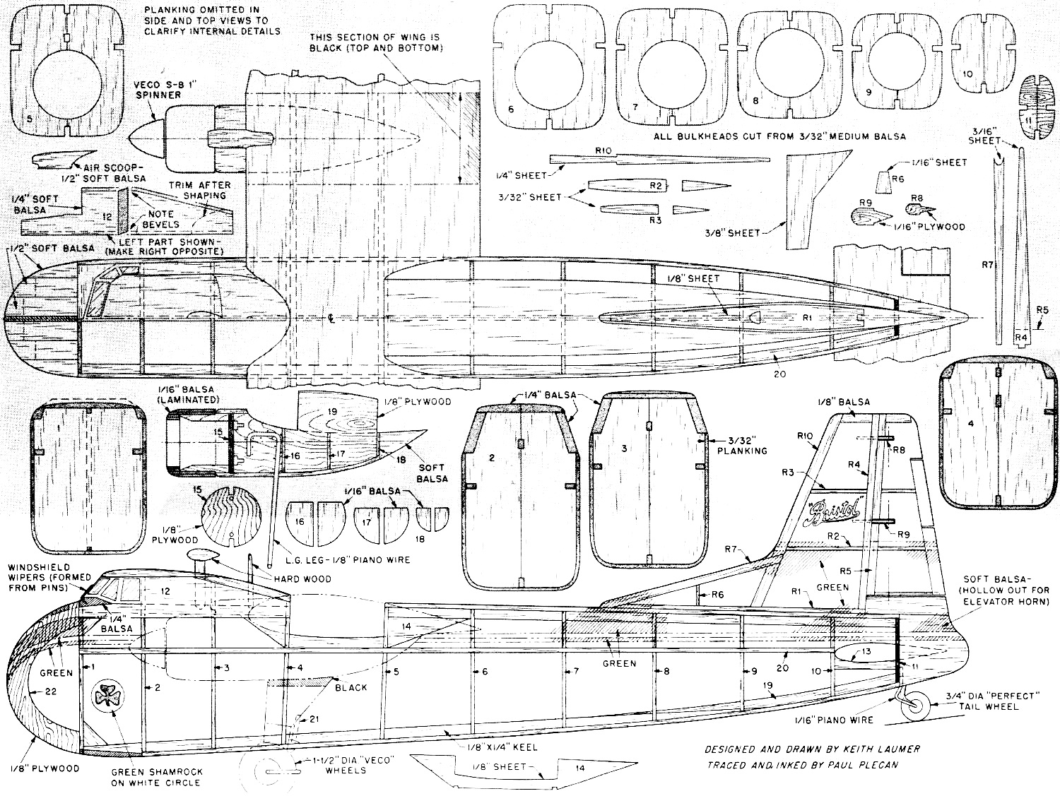
Start by cutting out bulkheads 4 through 10 from 3/32" balsa, split them down
the center. Layout 1/8 by 1/4 keels and part #14 on side view of fuselage. Add part
19 (1/8" balsa), and place one-half of each bulkhead in proper position, While cement
sets up, cut two of part 20 and make up the two side stringers. Remove half-shell
from plan and add other set of half bulkheads, place side stringers in notches.
Be sure to align fuselage carefully at this point.
Cut part 11 from 1/8 plywood and bind 1/16" piano wire tail wheel strut in place
with #30 linen thread, and install. Part #13 fits between 10 and 11 and the gussets
at the front against bulkhead 1 complete the basic frame.
 Start planking by cutting two side patterns
from medium 3/32" balsa. Cement them first against bulkheads 1 through 7; when set,
bend both in at same time and cement against bulkheads 8 through 11. Be sure to
place these panels against flat portion of bulkhead sides. Start planking by cutting two side patterns
from medium 3/32" balsa. Cement them first against bulkheads 1 through 7; when set,
bend both in at same time and cement against bulkheads 8 through 11. Be sure to
place these panels against flat portion of bulkhead sides.
Cut top rear panel as shown on top view, cement in place. Bottom panel is identical
except that it extends forward an additional 6-1/2". Complete planking using 3/32"
square strips. Cut two of #12 from soft 1/4" balsa and cement in position to form
cabin sides. Note that a left and right hand version of #12 is needed. Shape 1/4"
balsa 7/8" by 3" to cross section shown on side view to form lower part of cabin
and instrument panel. Cut rear section of cabin roof from 1/4" balsa and cement
in place; bevel top as shown on side view, add front roof section.
 Cut part 22 from 1/8" balsa or plywood,
add 1/2" soft balsa or white pine slabs to build up nose section. Cut tail fairing
from soft balsa block and cement in position; then use a sharp knife or razor to
trim all rough areas down. Finish shaping with a piece of #2 garnet paper wrapped
around a small sanding block. Sand lightly so as not to cut too much; when shape
is right, switch to successively finer grades of paper to work out a smooth finish.
Seal surface with clear fuel-proof dope of the kind you intend to use for the final
paint job, give fuselage a last going-over with 3/0 paper, and we'll move on to
the wing. Cut part 22 from 1/8" balsa or plywood,
add 1/2" soft balsa or white pine slabs to build up nose section. Cut tail fairing
from soft balsa block and cement in position; then use a sharp knife or razor to
trim all rough areas down. Finish shaping with a piece of #2 garnet paper wrapped
around a small sanding block. Sand lightly so as not to cut too much; when shape
is right, switch to successively finer grades of paper to work out a smooth finish.
Seal surface with clear fuel-proof dope of the kind you intend to use for the final
paint job, give fuselage a last going-over with 3/0 paper, and we'll move on to
the wing.
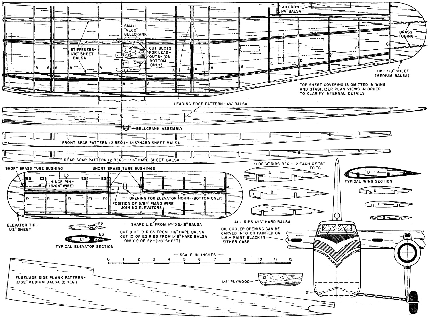
Use spar patterns to cut two of each spar from hard 1/16" balsa - don't cut the
notches yet. Carefully score and bend the blank spars to angles shown on wing plan.
Cut celluloid center layer for each spar, bend to fit, and using plenty of cement,
laminate the two spars. Clothespins are handy at this point to hold the layers together
while drying.
 Next, make up the leading edge, using medium
1/4" balsa. Carefully cut taper shown on wing front view and joint as shown on top
view. Cut stiffeners from hard 1/16 balsa, cement leading edge stiffener in place;
refer to rib pattern for positioning. Use spar patterns to mark positions of notches
on spar assemblies. Cut notches with a sharp razor, or on a power band or jig saw.
Cut ribs from hard 1/16" balsa, drill holes in one set for leadouts. Start wing
assembly by cementing ribs on rear spar - be sure your notches are sufficiently
deep so that ribs and spar are flush top and bottom. Fit front spar in place, add
spar stiffeners and 1/16 by 1/4 strip near trailing edge. Cut panels of medium 1/16"
balsa to exact size, and plank the underside of the wing, the center section and
outer wing panels being covered separately. Next, make up the leading edge, using medium
1/4" balsa. Carefully cut taper shown on wing front view and joint as shown on top
view. Cut stiffeners from hard 1/16 balsa, cement leading edge stiffener in place;
refer to rib pattern for positioning. Use spar patterns to mark positions of notches
on spar assemblies. Cut notches with a sharp razor, or on a power band or jig saw.
Cut ribs from hard 1/16" balsa, drill holes in one set for leadouts. Start wing
assembly by cementing ribs on rear spar - be sure your notches are sufficiently
deep so that ribs and spar are flush top and bottom. Fit front spar in place, add
spar stiffeners and 1/16 by 1/4 strip near trailing edge. Cut panels of medium 1/16"
balsa to exact size, and plank the underside of the wing, the center section and
outer wing panels being covered separately.
Give inside of wing a thorough coating of a 50-50 cement-dope mixture to strengthen
joints and seal structure against moisture - which can cause wing planking to buckle.
Install plywood panel for bellcrank, the leadout wires, and the 3/8" tapered strip
against which ailerons will fit, shaping as shown on detail of wing section. Plank
top of wing. (Use 50-50 mixture on underside of planking before installing). Cut
tips from 3/8" medium balsa and cement in place.
Shape leading edge and tips and sand out wing to smooth seamless finish. Apply
a coat of clear dope, and sand, and we can move on to the tail assembly.
 Cut out parts R-1 through R-10. Join R-4
and R-10 to R-1, and place ribs R-2 and R-3. Add R-6 and R-7, and cut planking to
exact shape shown on side view. Note that planking is fitted against rear face of
R-7 and R-10. The movable rudder is built up by cementing the ribs against one of
the 1/16" planking panels, cut to shape shown on side view, after which trailing
edge is beveled and other side added. Cut slots to receive R-8 and R-9, which are
cemented to fin after shaping. Rudder assembly can now be cemented to fuselage,
and 1/2" balsa fairing block fitted in place under movable rudder and shaped. Cut out parts R-1 through R-10. Join R-4
and R-10 to R-1, and place ribs R-2 and R-3. Add R-6 and R-7, and cut planking to
exact shape shown on side view. Note that planking is fitted against rear face of
R-7 and R-10. The movable rudder is built up by cementing the ribs against one of
the 1/16" planking panels, cut to shape shown on side view, after which trailing
edge is beveled and other side added. Cut slots to receive R-8 and R-9, which are
cemented to fin after shaping. Rudder assembly can now be cemented to fuselage,
and 1/2" balsa fairing block fitted in place under movable rudder and shaped.
Assemble fixed portion of elevator over plan, plank underside, add tips. Build
flippers, plank undersides and join with a piece of 3/64 piano wire bent to shape
shown. Note elevator horn is formed by bending down an extension at center of this
wire. The brass tube bushings must be slipped over the wire before final bends are
made. Cement outer axle wires in place, cover elevators. Install them in the stabilizer,
add top planking. Shape tips and leading edge, clear dope and sand.
Cut nacelle profiles, part 19, from 1/8" plywood, bend and attach landing gear
legs, using #30 linen thread, cement the bindings. Cut firewalls from 1/8" plywood
(use 3/16" ply for engines over .049 displacement); drill for engine mounting bolts,
or notch for beams, to suit power used. Add firewalls and formers 16, 17 and 18.
Cut slots in bottom wing covering to receive projecting tongues of parts 19, cement
nacelle assemblies in place on wing. Secure mounting nuts in place behind firewalls
or under beams, fuel-proof nacelle frames.
 Install tanks, if separate tanks are used,
with left tank slightly larger. Use medium 3/32" square balsa to plank nacelles,
fuel-proofing each strip before installing. Add soft blocks to complete rear contour
of nacelles. Build cowls by using a form (a round bottle of the right size, or a
piece of broom handle) and wrapping 1/16" sheet around it, beveling ends for a flush
lap joint. Use two layers of balsa, and add two narrow strips at the front, inside,
as shown on nacelle detail. Cut out an opening in each cowl after shaping to fit
over cylinder heads. Install tanks, if separate tanks are used,
with left tank slightly larger. Use medium 3/32" square balsa to plank nacelles,
fuel-proofing each strip before installing. Add soft blocks to complete rear contour
of nacelles. Build cowls by using a form (a round bottle of the right size, or a
piece of broom handle) and wrapping 1/16" sheet around it, beveling ends for a flush
lap joint. Use two layers of balsa, and add two narrow strips at the front, inside,
as shown on nacelle detail. Cut out an opening in each cowl after shaping to fit
over cylinder heads.
Carefully sand nacelles to a smooth contour and fuel-proof. Cut landing gear
fairings to shape from 3/8" medium balsa, cut slots in leading edge of fairings
to fit over L. G. legs, cement in place; then fill slots with 1/8" square.
Next, bend supporting strut to shape, following half-pattern shown on front view.
Note strut bends down at main leg, and around wheel on back side. Cut part 21 from
1/8" balsa and bind the strut to it, ready for installation.
Install elevator by cutting away rear fairing block from the fuselage, together
with bulkhead 11 and enough of the shell to allow elevator to fit into place. Then
cut a notch in amputated tip of fuselage to receive trailing edge of elevator (use
a length of hack-saw blade) and cement it back in place. Of course, the pushrod
must be engaged in the elevator horn and installed together with the elevator.
Trim away portion of wing forward of front spar, below leading edge stiffener,
and between the two ribs A on either side of centerline of wing. Cut away enough
of cabin sides (parts 12) to accommodate upper curve of wing. Tailor wing, behind
rear spar, to fit over fuselage. When complete, mount bellcrank, engage push rod,
and join wing to fuselage, checking alignment carefully.
Cut slot in bottom of fuselage to receive part 21 with L. G. strut attached,
and cement the assembly in place. Fill in slot with scrap balsa and sand smooth.
Don't solder the struts together yet; wheels have to be installed first. Cut air
intakes in wing leading edge.
Check the "balance" of the model now. It should balance on the front spar. It
may be necessary to drill a hole in nose section bottom and pack with modeling clay.
Plug hole and sand smooth.
Use Plastic Wood or balsa putty to fill in where needed, complete sanding of
airplane as a unit. Spray a coat of grey auto body primer over entire model, sand
out to a satin finish. Make radio antennae, ailerons, and airscoops, sand and prime,
and install. The movable rudder can either be cemented in place, offset slightly
to the right, or it can be mounted so as to be adjustable, by installing a wire
axle pivoting in R-8 and R-9.
When priming, filling, and sanding are complete to your satisfaction, spray a
coat of fuel-proof aluminum lacquer or enamel over entire ship. Sand as needed,
and repeat. Three well-sprayed coats should be enough. Tape off all except anti-glare
panel in front of cabin, nacelles and top of landing gear legs and portion of wing
indicated on plan, and spray black. Remove tape, mask all of model except decorative
stripes along each side, including fuselage top rear (see plan and photos) and spray
bright green. The lettering is cut from black Trim Film, and the shamrock insignia
from white and green. Install 1-1/2" Veco wheels on main gear and Perfect 3/4" tail
wheel, solder supporting struts to main gear.
Paint inside of cabin black; cut pieces of 1/64" plastic for windows, one for
front panels, and one for each side. Dope a small piece of stiff paper aluminum,
and cut mullion strips to go between window panels. Make windshield wipers from
pins and install.
Notch out and splice 5.5/3 props to make scale 4-bladders, and dope aluminum.
Add black edging; cut two more notches in Veco 1" spinners to fit them.
Try your first flights on a calm day, over a paved surface. The 170 is a real
floater in the glide, so here's your chance to perfect your scale take-offs and
landings. Ease her off and settle her in on all three wheels. And remember - no
loops.
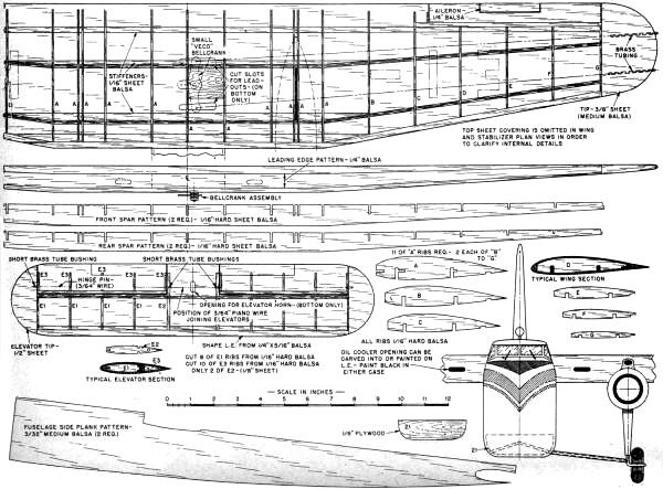
Bristol "170" Freighter Wing Plan
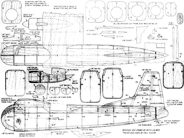
Bristol "170" Freighter Fuselage Plans
Notice:
The AMA Plans Service offers a
full-size version of many of the plans show here at a very reasonable cost. They
will scale the plans any size for you. It is always best to buy printed plans because
my scanner versions often have distortions that can cause parts to fit poorly. Purchasing
plans also help to support the operation of the
Academy of Model Aeronautics - the #1
advocate for model aviation throughout the world. If the AMA no longer has this
plan on file, I will be glad to send you my higher resolution version.
Try my Scale Calculator for
Model Airplane Plans.
Posted September 13, 2013
|