Airplanes and Rockets website visitor
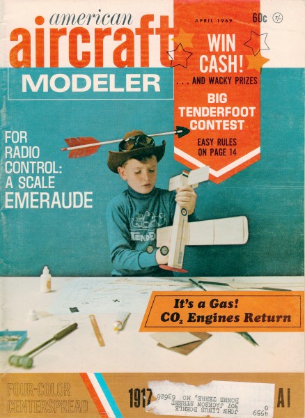
Ray L. wrote to say he has a Biceps control line model that appeared in the April 1969 edition
of American Aircraft Modeler magazine, and that he would like to have the
article posted. Per Roy, "I bought this model from one of our club members who is
a team race flier and built it on a whim, he fitted it with electric and had it
test flown by one of our aerobatic pilots and after that he lost interest it and
I was happy to give it a good home, the quality of build and finish is to pro standards."
Power in the original was a Fox .59, wingspan is 48". AMA Plans Service still prints the
Biceps plans.Biceps - A muscular, big-engine bipe for sport and exhibition control-line flying.
 By Donald Yearout By Donald Yearout
Nearly every airplane nut has a soft spot for biplanes. There is something nostalgic
about a two-winger, the whistle of wind through rigging wires and all that stuff.
When our local model club began control-line exhibition flying to stimulate public
interest and recruit new club members, I became enthusiastic about a bipe for that
type of flying. It would be an attention-grabber, an extremely stuntable and flashy
aircraft. The ship I had in mind would be large; a small plane just doesn't get
attention. The further I studied the biplane configuration, the more intriguing
it became.
It appeared that the built-in head-wind high-drag characteristic to biplanes
might be used to advantage. A large engine to turn a big low-pitch prop would give
a very high static thrust. In combination with the high-lift high-drag layout this
would result in a relatively slow-flying, extremely maneuverable craft - like a
helicopter with its rotor facing forward! And that's the way it turned out.
A few additional design features improved performance, such as: thick, blunt
airfoil sections with full-span flaps on both wings to help eliminate the wobbling
or staggering at low speeds common to biplanes during tight turns. A large elevator
surface proved effective at low speeds. A large rudder with quite a bit of turn-out
kept the lines tight at all times, since centrifugal force is not much of a factor
at low speeds. There you have it.
The theory sounded good, but the proof came in building and flying the brute.
Biceps is a spectacular performer, a real ball to fly. Although not a smooth, precision,
contest-type ship, it should give a good account of itself in any contest in the
hands of a competent pilot. For exhibition-flying, Biceps is superb, the hit of
any show. It is not particularly difficult to build. Large size and straight lines
contribute to simplicity. It does take a considerable amount of balsa.
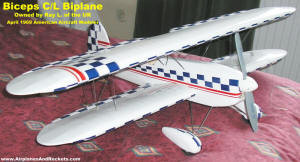
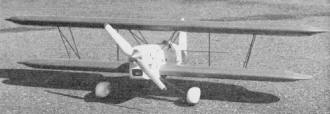
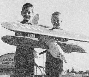
This completed Biceps is owned by Ray L., of the UK. He was kind
enough to send me the photo. He bought the model from a fellow club member. I would
never be able to part with such a nice airplane! (click for larger version)
High-lift, high-drag, with big prop, make the bipe fly like a
'copter with rotor facing forward.
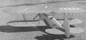
Oodles and gobs of wing area, thick airfoils and full-span flaps
add up to a precision in flight that must be seen to be believed. You'll look good!
Tail Surfaces: Both the fin-rudder and the stabilizer-elevator
assemblies are made from medium-weight sheet balsa; wood grain parallel to hinge
lines. First glue balsa sheets together edgewise to obtain enough width for entire
piece to be cut from. Then shape to a streamline section similar to that shown on
the plan. I have found that sanding boards (sandpaper of various grits glued to
a flat piece of 1 x 2" pine about 8 or 10" long) make excellent tools for rough-shaping
balsa wood before final sanding, prior to painting and finishing.
After rough-shaping, thoroughly sand with progressively finer sandpaper until
you are satisfied with the job. Then seal the wood grain with a couple of coats
of clear dope. I use and recommend Aero Glass products. They cost a little more
but the quality is worth it. A couple of coats of filler should be applied next,
again lightly sanding between coats. Now cut the rudder and elevator apart from
their respective assemblies and sand the cut edges, rounding them slightly and follow
by doping to seal the wood grain.
Now glue the rudder to the fin with 1" of turn-out measured at the trailing edge.
For the elevator, recess the edge as necessary for the control-horn assembly; I
used a prefabbed unit available at most hobby stores. Cement or epoxy the horn in
place. Next attach the hinges, cloth, metal, or plastic as you prefer - I used cloth.
Dope over them, seal, and fill the surface. A drop of oil applied to the center
of each hinge before doping will keep them flexible. The final finish coats of dope
will be applied after the surfaces are attached to the fuselage.
Wings: There isn't anything unusual in their construction except
for the wing-strut-attachment method, which will be explained in detail later. First
cut out the ribs. You may think there are a lot of them and there are, but the close-rib
spacing really looks nice on the completed ship; it serves a real purpose too. On
a thick airfoil, close-rib spacing is necessary to prevent the covering from sagging,
which would defeat the purpose of the thick airfoil. Cut the ribs from medium-soft
1/16 sheet balsa. I made metal templates for the W1 and W2 ribs, so I could cut
out about a dozen at a time which helped somewhat.
Make up the wing spars from hard, straight balsa - 1/4 x 1" for the front spars
and 1/4 x 3/4" for the rear. Splice as necessary to gain the proper lengths. Slide
the full-length ribs, one at a time, onto both the front and rear spar making sure
you do not forget the W3 center rib in the top wing and the W7 rib in the bottom
one. When the ribs are in their approximate position, pin the spars down directly
over their corresponding plan, blocking them up to clear the ribs with balsa scraps
- 1/8" thicker scrap under the rear spar than the front. Next, slide the ribs into
their exact positions and spot-glue them in place. Later you can cement more thoroughly
after removing the wing from the plan.
The trailing edges can be installed next. They may be shaped either before or
after attaching. I used a razor plane on the original model which worked very well.
Next put on the 1/4 x 1 leading edges after beveling one edge of each so they fit
together nicely. Before trimming the leading edges to final shape (again using a
razor plane or substitute), install all the false ribs (W2, 5 & 6) in their
proper positions and cement thoroughly. Make darned sure you don't forget to put
in the wing strut mounting blocks (made from 1/2" hard sheet balsa). Cement them
thoroughly in their proper locations - bottom of the top wing, and top of the bottom
wing.
Install the wing tips and other finishing pieces such as top wing center-section
trailing edge and bottom wing center-section trailing edge and bottom wing center-section
sheeting. Carefully sand entire structures, dope and sand again. The wings should
now be ready for covering. I used silk on the original ship for durability although
other covering materials may be used as well. Dope with three coats of clear and
two of color for reasonably good finish, substituting a coat of filler for the third
clear coat if desired.
Fuselage: Make the engine mounts first, using very hard wood
(maple was used on the original Biceps). Each mount measures 3/8 x 3/4 x 12 1/8".
Drill the mounting holes to fit the engine you are going to use. A Fox 59 was used
in the first Biceps and worked out beautifully - a very powerful, depend-able engine.
Also drill the cabane strut in the location shown on the plan. Now mount the engine
on the mounts using #6-32 machine screws. A small amount of out-thrust can be added
at this time if desired, although it is not absolutely necessary.
Next cut out the 1/16 plywood doublers and the 1/8 ply firewall (patterns are
shown on the plan). Place the firewall in position on the mounts and apply epoxy
glue to the joined surfaces. Lay the mounts upside down on a flat surface with the
engine and firewall top hanging over the edge. Use a piece of wax paper or plastic
wrap under the mounts to keep the epoxy off the surface. Glue the 1/16 plywood doublers
to the engine mounts and firewall with more epoxy and then let everything cure.
Now cut out the 1/8 fuselage sides and 1/16 balsa doublers (grain-vertical on
the latter) from medium-weight sheet balsa. Then cement the 1/16 doubler pieces
against the inner surface of the 1/8 side parts; be sure the cutout for the lower
wing is cut out through both parts. Now cement fuselage side assemblies to the plywood
doublers, putting on formers F1 and F2 at this time. After allowing the glue to
dry overnight, bring the aft ends of the fuselage together and cement them with
a wedge of scrap balsa for reinforcement. Install the rest of the fuselage formers,
bellcrank and mount assembly and landing gear mount.
Attach a couple of 6-32 nuts to the upper surface of the gear mount while you
can still get at it. Do not put the top and bottom sheeting on yet. You can, however
fit the fuel tank in and build up a supporting plate of balsa underneath and on
top. I used a plastic "clunk" R/C tank in my Biceps, but a metal control-line tank
could be used as well. One advantage to the plastic tank is that it is removable
for repair or replacement through the round hole in the firewall. If a metal tank
is used, the firewall hole may be eliminated. No fuel tank fill and vent lines are
shown on the plans because of the option of tank type used.
Landing Gear: This is made from 1/8 spring aluminum stock. A
Sig landing-gear blank was used on the original model. The aluminum spring stock
is cut to size and bent to shape as shown on the plan, being very careful to use
large radius bends. A small radius bend will very likely crack the hard aluminum
stock, in which case, you've had it. Nothing to do but start over again with another
blank. The wheels are attached with No. 8 machine screws (see plan for details).
The wheel pants are built up from three laminations of balsa with a plywood insert
in the side between the wheel and gear leg. Use epoxy glue between the plywood insert
and landing gear leg, and epoxy putty to fillet in for extra strength to finish
off the job. You will probably have to drill out the wheel hubs with a #19 drill
to make them fit a No.8 machine screw since most wheels have smaller hub holes than
that. Mount the gear on the fuselage with two No. 6 flat head machine screws, counter-sinking
the heads flush with the surface.
Miscellaneous Assembly: Install the lower wing. Before you slide
it through the holes in the fuselage however, put wing flap horn into position.
The flap horn is made from 3/32 music wire. The sheet metal lever arm is silver-soldered
to it. Glue the wing in position and connect the bellcrank to the flap horn. Install
the flaps by attaching the hinges (fabric or metal).
Now install the stabilizer and attach the elevator to the flap horn. Thoroughly
check out the control system and modify as necessary before going further. Next,
install the tail wheel and mount. Before going further, all four wing struts must
be built and attached. The struts are made from music wire as shown on the plan.
Spiral wrap all tips with copper wire and solder all joints. Now see if you can
fit the bottom ends of the cabane struts into the corresponding holes in the engine
mounts. If you can - great! If not, bend the struts to fit or enlarge the holes
in the engine mounts.
Place the interplane struts into position in the lower wing and fit the top wing
onto all the strut tips. Make a couple of cardboard jigs (shown on the plan) to
align the top wing properly. When everything fits, epoxy the lower ends of all the
struts into their mating holes and allow to cure undisturbed. Remove the top wing
and install the top and bottom sheeting on the fuselage. Round all corners and edges,
install the rudder, and start applying the finish. At least two coats of clear followed
by filler and color coats. Attach the top wing again, using the cardboard jigs and
the old faithful epoxy. After attaching the top wing flaps, install the flap linkage
rods and make sure they work without binding.
Build the flap linkage rods from 1/8 brass tubing flattened slightly to an oval
shape. Cut length carefully so the flaps will be even and parallel. Drill 1/16 holes
through the rod tips so they will end up at least 1/16 below the flap surface. The
hinge pins at both ends of the flap rods are 1/16 music wire, 7/8" long. The tubing
pieces that complete the assembly are 1/16 ID x 1/16" long, either brass or aluminum.
Grease the rod tip, hinge pins and tips of the tubing (not the center) with Vaseline.
Place the assembly in position in the grooves in the flaps and cover with epoxy.
Try to keep the epoxy away from the oval rods to prevent binding later. It is much
easier to do the lower wing hookup first, then after that is cured, turn the ship
over and repeat the hookup to the top wing. Be certain that the flaps are even and
parallel before the last hookup is made. It is darned hard to correct later.
Build the cowling from sheet balsa, being sure to dope generously inside. The
cowling may be attached using a couple of screws through the side into the engine
mounts. After completing all the little details like the spinner, windshield, line
guides, etc., it should be completed. Nothing left but some spectacular flying.
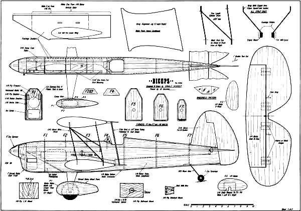
Biceps Plans Sheet 1
<click for larger version>
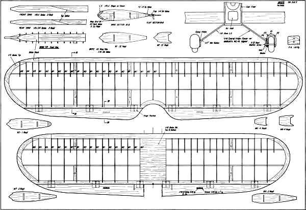
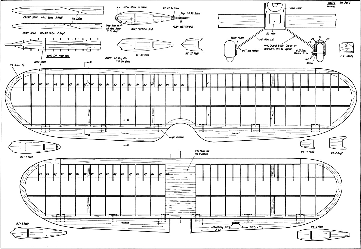
Biceps Plans Sheet 2
<click for larger version>
Notice:
The AMA Plans Service offers a
full-size version of many of the plans show here at a very reasonable cost. They
will scale the plans any size for you. It is always best to buy printed plans because
my scanner versions often have distortions that can cause parts to fit poorly. Purchasing
plans also help to support the operation of the
Academy of Model Aeronautics - the #1
advocate for model aviation throughout the world. If the AMA no longer has this
plan on file, I will be glad to send you my higher resolution version.
Try my Scale Calculator for
Model Airplane Plans.
Posted September 20, 2023
(updated from original
post on 7/16/2012)
|