|
When I first saw this "U-Control
Model Plane" article in a 1952 issue of Popular Mechanics magazine, I expected
it to have been written by one of the
Stanzel brothers. Long after their entry into the model airplane manufacturing
world, Joe and Victor created their line of
battery-powered, electric motor-driven control line models in 1958. It eventually
included a helicopter, a monoplane, and a flying saucer, amongst other craft. The
Stanzels, BTW, invented the Monoline control line system which was adopted by U-control
(aka control line) speed modelers because it created much less aerodynamic drag,
facilitating higher airspeeds. Maybe this article was a motivation for the Stanzels
since it predates their product line. I personally had both the
ElectroMic Tethered "Flash" airplane and the
ElectroMic
Tethered "Copter" helicopter back in the late 1960s. Anyhoo, this would make
an interesting project for your kids.
U-Control Model Plane
 By Kai M. Klemm By Kai M. Klemm
Powered by a novel electrically driven remote-control unit, this tiny plane will
fly level, zoom and loop on a circular course in a small living room. The control
unit, which also supplies power, is housed in a mailing tube about the size of an
ordinary flashlight, except that it is slightly longer to accommodate four flashlight
dry cells and a tiny electric motor. The motor drives the propeller through a "flexible
shaft" of fine piano wire, the length of the wire depending on the radius of the
flight space available. Because of the constant speed of the left-hand prop and
the connection of the flexible shaft to the fuselage at its center of gravity, the
plane maintains level flight without any tendency to nose down due to torque.
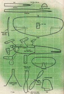
All parts of the plane are made of balsa-wood, except, of course, the angle drive
and the landing gear. Sheet balsa, 1/16 in. thick, is used for all parts except
D, E and F in the details on the following page. The sides of the fuselage are made
first, then the bulkhead, A, is glued in place. Next, both the sides are glued together
at the tail and cowl block, C, is glued in place. The landing-gear frame is bent
to fit inside the fuselage and must be cemented in place before the bottom is put
on. The inclination of the frame is shown by dotted lines on the details. After
gluing on the bottom, the fuselage is sanded to contour and sides are slotted for
the stabilizer. Now make the wing, stabilizer and fin, but do not attach the wing
until the angle drive is in place.
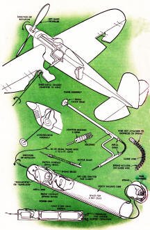
 The details on the opposite page show the
assembly of the angle drive and how it is placed in the plane. The drive housing
consists of two pieces of 1/16-in. o.d. brass tubing held at right angles by a brace
of brass wire to which the housings, or sleeves, are soldered. The piano-wire shaft
from the motor is passed through the short sleeve so that the end projects. A thin
metal disk about 3/16 in. in dia. is soldered to the end of the wire. Then a length
of the piano wire is inserted in the long sleeve, cut to required length, and a
3/16-in. metal disk is soldered to the end. The flexible connector between the two
shafts is made as in the right-hand center detail on the opposite page. The drive
is made through a fine coil spring of the type and weight found in camera-shutter
releases. The ends of the spring are soldered to short bushings cut from 1/16-in.
o.d. brass tubing and the outer ends of the bushings are soldered to the metal disks
at the ends of the flexible shafting. Before soldering the bushings to the metal
disks, pass a length of spring-brass wire through the bushings and the coil spring
and bend to a uniform curve, cutting to length as required. When the assembly is
made and all parts have been soldered in place, the spring and bushings turn on
the curved-wire guide. In this manner power from the flexible shaft is transmitted
at right angles without buckling the spring. Care must be taken in assembling to
assure that the curved wire is free at the ends and that the metal disks do not
bind against the ends of the short and long sleeves. Adjust the unit by bending
the wire brace until it turns freely. The details on the opposite page show the
assembly of the angle drive and how it is placed in the plane. The drive housing
consists of two pieces of 1/16-in. o.d. brass tubing held at right angles by a brace
of brass wire to which the housings, or sleeves, are soldered. The piano-wire shaft
from the motor is passed through the short sleeve so that the end projects. A thin
metal disk about 3/16 in. in dia. is soldered to the end of the wire. Then a length
of the piano wire is inserted in the long sleeve, cut to required length, and a
3/16-in. metal disk is soldered to the end. The flexible connector between the two
shafts is made as in the right-hand center detail on the opposite page. The drive
is made through a fine coil spring of the type and weight found in camera-shutter
releases. The ends of the spring are soldered to short bushings cut from 1/16-in.
o.d. brass tubing and the outer ends of the bushings are soldered to the metal disks
at the ends of the flexible shafting. Before soldering the bushings to the metal
disks, pass a length of spring-brass wire through the bushings and the coil spring
and bend to a uniform curve, cutting to length as required. When the assembly is
made and all parts have been soldered in place, the spring and bushings turn on
the curved-wire guide. In this manner power from the flexible shaft is transmitted
at right angles without buckling the spring. Care must be taken in assembling to
assure that the curved wire is free at the ends and that the metal disks do not
bind against the ends of the short and long sleeves. Adjust the unit by bending
the wire brace until it turns freely.
The angle-drive unit is assembled in the fuselage as in the upper detail on the
opposite page. First glue part B in place, then cement the long sleeve, or propeller
shaft bearing, to it. Note that a part of the brace and the short sleeve project
from the opening in the side of the fuselage. Next, sand the wing to the airfoil
indicated in the detail and cut out and hinge the ailerons with lengths of fine
copper wire. Cement the wing in place on the fuselage with a 3-deg. angle of incidence.
Then add the rear cowling, E, the windshield and headrest fairing. As the final
step in this assembly, bend a bracket bearing from sheet brass and drill a hole
for the piano-wire shaft near the end of one arm. Then slip the bracket over the
wire and cement it to the underside of the wing as shown.
 The power unit, shown in the lower details
on page 188 consists of a mailing tube divided into two compartments, the smaller
housing the motor, with its shaft projecting through an oversize hole in the cardboard
disk which is cemented or taped to the end of the tube. A coil spring about 1 in.
long and of the same general characteristics as that used in the angle drive is
used to form a flexible connection, or universal joint, between the motor shaft
and the piano-wire shaft. In order to make the connection it will be necessary to
solder a suitable bushing to the end of the piano-wire shaft as shown in the detail.
Then the spring is slipped over the bushing and soldered. It is not soldered to
the motor shaft, as a tight fit is sufficient to transmit the full power of the
motor. The power unit, shown in the lower details
on page 188 consists of a mailing tube divided into two compartments, the smaller
housing the motor, with its shaft projecting through an oversize hole in the cardboard
disk which is cemented or taped to the end of the tube. A coil spring about 1 in.
long and of the same general characteristics as that used in the angle drive is
used to form a flexible connection, or universal joint, between the motor shaft
and the piano-wire shaft. In order to make the connection it will be necessary to
solder a suitable bushing to the end of the piano-wire shaft as shown in the detail.
Then the spring is slipped over the bushing and soldered. It is not soldered to
the motor shaft, as a tight fit is sufficient to transmit the full power of the
motor.
The battery compartment of the tube is closed at the lower end with a friction
cap made of sheet brass. Two terminals and a compression spring are fitted in the
cap and the positive terminal is insulated from the metal. After wiring and installing
a switch and dry cells, test the assembly for smooth operation without the prop.
If there is any tendency toward vibration, the cause must be found and corrected
before the assembly will operate satisfactorily. Cut the prop to the size indicated
from thin sheet aluminum, give it a left-hand twist and mount on the prop shaft
with a small disk of sheet metal to which a short length of 1/16-in. brass tubing
has been soldered to form a hub. If available, a small gear wheel from a clock is
just the thing. Fit the prop with a balsawood spinner as in the details.
Flying the plane is quite simple. Once in the air it is controlled by arm movements.
Successful maneuvers depend on the application of power at the proper time and also
in the guidance of the hand and arm. Experimentation with elevator and aileron settings
will be necessary.
Posted August 31, 2024
|


