|
1961 was really only in the
dawn of the Space Age,
with the first successful communications satellites having been launched just a few years
earlier in 1957. The first suborbital rocket launch occurred in 1944 when the Germans sent
a V-2 rocket above the
Kármán line (100 km,
62 mi) which separates Earth's atmosphere from outer space.
Albert II,
a rhesus monkey, was the first primate to reach space aboard a V-2 in 1949. Technology was
moving pretty quickly in the aerospace realm, both with airplanes and with rockets. Model
rockets were a big thing for boys (and a few girls) of the era, and similar advances in materials
and methods were being reported in the pages of American Modeler and other magazines.
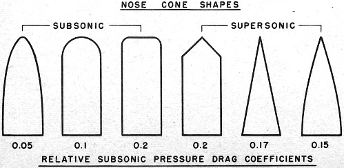
The chart here of drag coefficients of various nose cone shapes is really interesting, but
not surprising to someone with a fair exposure to aerodynamics. G. Harry Stine was a
big part of the scene and wrote many extensive articles and books on the subject.
Model Rocketry's New Look
By G. Harry Stine
 There is a "new look" to model rockets that is allowing
them to fly higher, faster, and better. There is a "new look" to model rockets that is allowing
them to fly higher, faster, and better.
This new look does not come about because of any improvement in available model rocket
engines or kits. It stems from over a year of hard design work, wind tunnel tests, and flight
experience. The result has been a terrific increase in model rocket performance and a whole
new set of NAR national model rocket records.
Until about a year ago, we all designed and built our model rockets to look like their
big, supersonic counterparts which flew from Canaveral, White Sands, or Wallops Island. Nose
cones were sharply pointed and angled. Fins were made with sharp leading edges and bluff or
blunt trailing edges. The high-performance models of that time were short and squat. In reality,
model rockets were really scaled-down "big ones."
It was John Bonine, the 1960 National NAR Champ, and his father, Jim; who first got the
notion that maybe this wasn't the way to design model rockets. Wind tunnel tests on model
rockets began to indicate. that something was wrong with design.
Relative subsonic pressure drag coefficients.
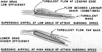
Supersonic & subsonic airfoil at low/high angle of attack at subsonic
speed.
The Aerodynamics Department of the Air Force Academy had made some wind tunnel runs on
Aerobee-Hi models at 50 mph air speed. The data was amazing: it showed that the drag on the
Aerobee-Hi model was quite high and that its drag coefficient was on the order of 10 to 15
times higher than for the big Aerobee-Hi. Furthermore, as angle of at-tack was increased,
drag rose alarmingly and seemed to indicate that the fins were losing effectiveness, stalling
at very low angles of attack.
The wind tunnel tests showed a total drag of over 2 ounces at 100 mph and 50 angle of attack.
Since the model weighed 1.3 ounces, it didn't take a genius to see that drag was really cutting
into the performance.
Then it became obvious that the old Carlisle Mark II model with its round nose cone and
several other designs with round noses were out flying most of the sleek scale models. They
didn't look like they could or should outperform the models based on prototype missiles.
"Quick, Watson! Bring my aerodynamics book!"
The bull sessions started, and soon new words and phrases were heard on rocket ranges and
in workshops - Reynolds Number, NACA, pressure drag, boundary layer, turbulent flow, induced
drag, and ballistic coefficient. It finally occurred to all of us in early 1960 that our concepts
were on the wrong hack.
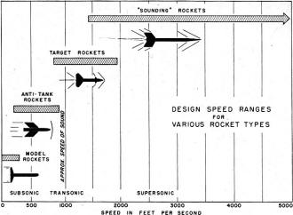
Big rockets are designed to fly most efficiently at supersonic speeds. They take off subsonically,
but spend most of their flight at better than Mach One in a flight regime known to aerodynamics
as "compressible flow." The air is treated as a compressible substance capable of forming
shock waves.
But our little model rockets rarely exceeded Mach 0.25! They always flew subsonically in
the "incompressible flow" regime where you can think of the air in the same terms as water.
Air flow properties at subsonic speeds are considerably different than at supersonic speeds.
A study of some NACA reports indicated that our sleek, pointed, sharp-edged subsonic model
rockets had all the drag characteristics of a barn door.
This was the clue to the "new look." Since our type of model rockets always flew in the
low subsonic speed range, we must therefore design model rockets for minimum drag characteristics
in that flight regime.
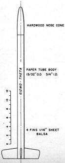
"Gizmo-Theta" by author is for NAR Type A or B engine (Rock-A-Chute manufacture).
It was easy to find those shapes having very low subsonic drag. Model airplanes had used
those shapes for years! In fact, once we all got used to the idea, the "clunk" appearance
of model rockets is no more unusual than some of the shapes of model airplanes, which don't
look too much like real airplanes in some cases either. (Whoever saw a full-sized airplane
that looked like a pylon free-flight job?)
There are several kinds of drag forces exerted on any object moving through the air - pressure
drag, friction drag, induced drag, and parasite drag, to mention some. A model rocket has
darned little parasite drag ... most of them are very clean. Pressure drag can be reduced
by using the right shape; friction drag can be reduced by a very smooth, glassy finish; induced
drag can be cut down by proper shaping of the fins.
The optimum nose cone shape for a model rocket is a parabola of revolution having a length
two to four times its base diameter. This shape has a constant pressure profile over its surface.
A simple hemispherical nose cone is second-best. It has very low pressure drag at nominal
angles of attack. Because of the constant pressure characteristics of a parabolic nose cone,
the flow about it is laminar, which means that the drag is low. Flow separation causing laminar
flow to become turbulent flow with higher drag can more easily occur at low angles of attack
on a conical or pointed nose cone. All of this sounds very erudite, perhaps, but in high-performance
model rocketry, every little bit counts.
The purpose of fins on a model rocket is to provide stability, and they do this by producing
lift in the strict classical sense of the word. Lift is really defined as the aerodynamic
force which acts at right angles to the surface. Lift created by fins produces an aerodynamic
moment which causes the angle of attack of the model to become less; when the angle of attack
becomes less, the model flies straighter with less drag.
The "old" fin airfoils with their sharp leading edges stalled and lost efficiency at very
low angles of attack. We can hear some of the old model airplane boys chuckling now. The boundary
layer actually separated right at the leading edge and then reattached itself further back
on the fin chord. We discovered that under these conditions, it was as though 25 to 40% of
the fin wasn't there at all!
The answer was a laminar flow airfoil on a fin. This could be obtained by rounding the
leading edge and tapering the trailing edge - no easy task with a 1/16" balsa sheet, by the
way, but some of the boys are doing it with 1/32" sheet balsa fins! With this type of airfoil,
the boundary layer did not separate and cause turbulent flow until much higher angles of attack
were reached, and then the boundary layer separated at the aft portion of the fin just as
in the classical airfoil case. This meant a more efficient fin. Therefore, less fin area could
be used. Therefore, less weight to the rocket. Q.E.D.: better performance. Less fin area was
doing more work.
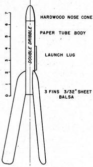
"Double Dribble" by John Bonine, National Association of Rocketry's (NAR)
1960 Champion.
A lot of work was done by Dan and Frank Oberhausen to reduce the induced drag of a fin.
Fins, being airfoils, create a vortex sheet starting at the tip of the fin when the fin is
producing lift. It isn't much, but again let us remember that every little bit counts in model
rocketry. The induced drag from the tip vortex is primarily caused by span-wise flow over
the fin. There are many ways to reduce this to practically nothing. Tip plates and fences
can be used, but they add weight and interference drag. A better way is to keep the leading
edge sweep back to a minimum or nothing, to keep trailing edge sweepback to nothing, and to
taper the fin tip in the manner of an airplane wing.
John Bonine used another approach: allow the entire flow over the fin to be span-wise flow
by using extreme sweepback on both leading and trailing edges. In other words, let the fin
tip also become the trailing edge!
There have also been some attempts at boundary layer control on model rockets to keep the
air flow straight around the tail section and to reduce the interference drag which is generated
in that region by the fins and body junctions. It's quite hard to judge at this time how effective
this has really been, although John Bonine did fly a finless model with nothing by six flow-straightening
fences made of 1/16" square balsa strips around the tail. (Don't do it; it's pretty tricky!)
Fins, after all, are the nastiest things about model rockets. They break off on landing
with great regularity. But, more important in this case, they create better than 50% of the
drag of a model rocket.
Why? A model rocket is quite small. Therefore, its Reynolds Number is very low. To put
it another way, the air flowing past it acts as though it were very soupy or viscous. Reynolds
Number is partially a function of the length of the moving body, and fins have considerably
less length or chord than any other part of the model. Therefore, their Reynolds Number is
very low indeed.
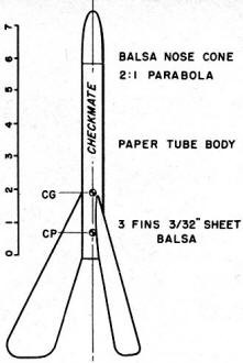
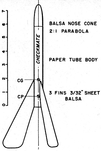
"Checkmate" by Bonine grew from Double-Dribble series. Holds NAR Class
2-B altitude, duration marks.
This Reynolds! Number proposition is the reason why model rockets have gotten longer and
slimmer: higher Reynolds Number and less drag. There is also the matter of a longer rocket
having higher fin moments and restoring forces and a longer oscillation period. It's harder
for a wind gust to cock a long model over, and a long model snakes through the air with less
angle of attack. But we digress, getting into very far-out dynamics here.
The typical model rocket now looks like a clunker. It doesn't look the way a rocket "ought
to look." But it is a triumph of low-speed ballistic body design, something nobody else has
had to worry about. Who would consider the low-speed end of the flight spectrum for rockets
or artillery shells other than model rocketeers; professional rocketeers couldn't care less,
since they are interested in Mach 20 instead.
However, model rockets aren't really ugly when you understand why they are built the way
they are. Take the Hitch-Stine "Gizmo-Epsilon," holder of the NAR Class B Payload Record of
637 feet. It's long and slim; without payload or motor, it weighs less than 0.5 ounces. It
grosses at about 1.9 ounces at takeoff. The basic design, evolved over a three-year period,
is so good that it is rare if a "Gizmo" model does anything except go absolutely right straight
up.
And John Bonine's "Double Dribble" designs are beautiful in performance, although some
people are inclined to doubt it. The "Double Dribbles" have turned out to be the most universal
contest models yet developed; they have flown in nearly every NAR competition class, sometimes
changing their classification by merely the addition of a different nose cone. Using "Double
Dribble" birds, Bonine set NAR national records in Class 1-B Altitude, Class 2-B Altitude,
Class 4-AB Altitude, Class B Payload, and Duration. Two of these records still stand.
What about the mirror surface on the "new look" models? Very good reason. Because their
very low Reynolds Numbers mean they are flying through very sticky air, boundary layer separation
and drag can be caused by surface imperfections as small as 0.01"! A rough finish on a nose
cone could bring back all the drag you were trying to get rid of by subsonic streamlining
in the first place!
Posted August 12, 2017
|