|
This article was scanned from
the 1961 American Modeler Annual edition. The magazine has been out of
print for decades, and is difficult to access unless you are fortunate enough to
buy one off of e-Bay. Hopefully the original authors won't mind my reprinting "Secrets
of 'Winning' Airfoils" here, but if they do, I will remove it. Airfoil plotting
goes back to the NACA (National
Advisory Committee for Aeronautics) days of white shirts, neck ties, thick-rimmed
glasses, and slide rules. Drawing boards, straight edges, and French curves which
were in use since the days of the Wright Brothers eventually got replaced by
software, but all the pioneering work was done by engineers with
shirt cuffs smudged with pencil lead. Consider this a window for a look back in
history.
Secrets of "Winning" Airfoils - F.A.I. Free Flighter in an exclusive
report
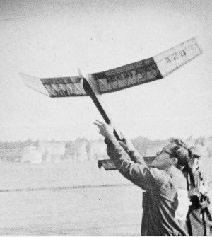
Lawrence H. Conover of Cedar Rapids, Iowa, and member of America's
1960 F.A.I. Power Championships free flight team launches his entry at Cranfield,
England, in finals. Along with four other contenders Larry was crowned as "joint"
competition champ.
Larry Conover, 1960 World Champion
How to make it fly like a bird? This was the pressing question for aerial experimenters
of long ago. And still is for model designers of today!
In ancient times they said, "Make the wing liken to a bird."
But it seemed that any direct copies of bird sections flew no better than those
experiments done via gliding a dead stuffed bird, wings braced out stiff.
Actually they were on the right track. Just lacked a few of the other essentials
needed for man to fly.
There was some secret of flight that only the birds knew. Many men watched, and
studied, and experimented. The Wrights among them. The Brothers solved the big problem
... stability and control. They found, to their surprise, that the best gliding
angle a buzzard could maintain was parallel to a seven degree slope. The Wrights
could do it on six degrees. Of course this was in cool air.
But as the wind picked up, or the heat of the sun warmed valleys and hillsides,
the birds became unbelievably efficient. "f.hey soared upward on wings apparently
locked out stiff. In effortless wheeling circles, became -pin points against the
clouds.
This was too much for man to solve, at least for the moment.
So the practical beginners stretched cloth over one side of a supporting framework.
(Like a kite.)
Lilienthal soon discovered that a certain amount of curvature gave better
results than a flat surface.
The Wright brothers found that Lilienthal's measurements of "lift and drift"
for certain airfoil curvatures were incorrect. In the first wind tunnel they worked
out the proper sections for their "Flyers."
Later, both sides of the wing were covered so the spars wouldn't stick out. .
And when faired in properly, it produced a pleasantly streamlined shape.
Between 1912 and 1920 most wing sections were designed around spars and structures.
Eyeballed smooth with a French curve.
Airfoil plotting
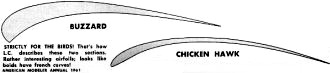
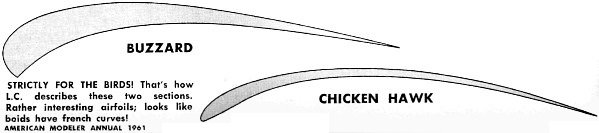
Strictly for the birds! That's how L.C. describes these two sections.
Rather interesting airfoils; looks like 'boids' have French curves
M. Joukowsky, during the First World War. derived his airfoil shapes mathematically.
These were systematically tested at Goettingen. Modifications of these sections
bear the name of Goettingen.
Well, modern aerodynamicists still don't know all the secrets of bird flight.
But they have discovered a few things about stiff wings.
One of the most important facts to the model designer is that he must work in
a Reynolds Number range below freezing. RN below 100,000. There are few measurements
of full-scale wing sections that fall in this range. In fact, most of them are over
ten times higher!
For that reason very few full-scale measurements give a true picture of what
is going on in the model airfoil range. In addition, there is quite some difference
between artificial wind tunnel air and the free air the birds fly in.
Therefore you must rely on proven sections, or those developed especially for
model aircraft. The following thirty-three airfoils will give you something to fit
any occasion.
For those who are not completely familiar with the method of plotting a section,
I will show you briefly one way to do it.
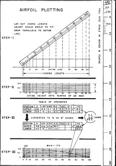
Refer to the page on Airfoil Plotting. A full size scale is drawn for you. Cut
it out and glue lightly to a piece of hard sheet balsa, 1/16 x 1/2 x 11 inches.
Step One: Note that the chord length is 100%. All measurements
of your drawing will be based on IT.
The graduated part of the scale is ten inches long. Place the "P" end of it at
the leading edge "0" point, scale parallel with datum line. Using this point as
a pivot. raise the scale until the 100 mark lines up with all extension' of the
trailing edge chord mark. Continue as directed.
Step Two: Your scale is graduated in tenths of an inch in that
section only from 10 to 20. Use this portion to mark off the ten graduations in
height. (Thickness of airfoil.) You can add to the original ten tenths of an inch,
and will find it necessary to do so on some of the sections which extend below the
datum line. (They will have minus numbers.) Or on sections which exceed one inch
in thickness.
Step Three: Now comes the fun.
If you don't know how to multiply on a slide rule, this is the time to ask an
engineer friend, or your math teacher. Or even the clerk at the drafting-supplies
store. He can teach you in ten minutes - on a two dollar slide rule - enough to
save you hours of tedious long multiplication.
Wing Sections for Rubber Models
Wing Sections for Nordic Gliders
Wing Sections for Powered Models
However, if you choose an even chord length you can do much of the work in your
head.
Now make up a data sheet with only the stations marked in. You must fill in the
upper and lower values from calculations of the ordinate multiplied by the chord
length.
An example for station 70 shows the product of an eight inch chord times the
upper ordinate 6.2 equals 49.6 (hundredths of an inch). This is very close to 50
hundredths of an inch, which is, of course, one half inch.
In practice it is very doubtful that you could mark off to closer than one hundredth
of an inch. So generally you can round off the figure following the decimal point.
Don't let the placement of decimal points worry you too much. When you mark the
dots for the airfoil curve, you will quickly see what range you should be in.
Keep your pencil sharp, preferably a 6H drawing pencil. It may help you to encircle
each plotted point as you transfer the calculated number from the data sheet onto
the curve.
You'll find it's fun to get the hang of estimating distances down to a hundredth
of an inch with only your pencil point. Your eye has amazing accuracy, when trained
just a little.
Now how about those airfoils?
Nordic Glider:
You will-soon find that many of these sections are by Georges Benedek. He has
done outstanding experimental model research at the Hungarian Modeling Institute.
His airfoils are the latest development in this field, and the most popular in Europe,
Many of the record holding models use Benedek sections.
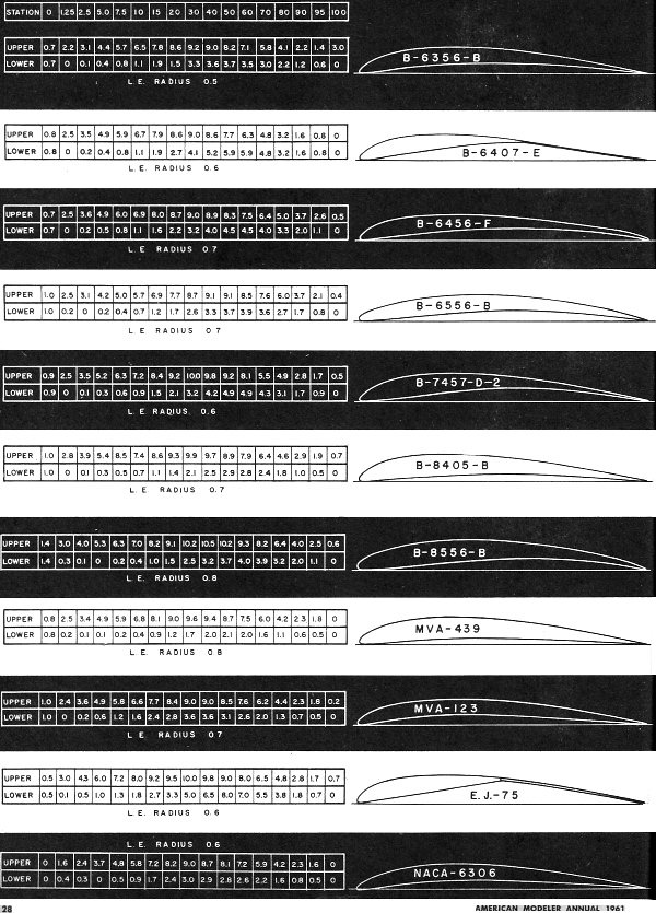
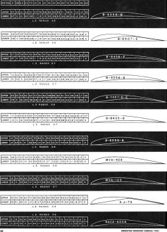
B-6356-b. A popular Nordic and Wakefield section for more than ten years.
B-6407-e. A Benedek modification of an airfoil by Erich Jedelsky, having a long
flapped trailing edge. External rib bracing (underside) on thin plywood, or very
high quality C stock balsa sheet, are requirements for this type of construction.
B-6456-f. Used on some of the best Hungarian A-2 models.
B-6556-b. A variation of the popular 8556. A bit sensitive in pitch.
B-7457-d-2. A modification of the thin flapped T.E., which allows more internal
structural support.
B-8405-b. A general purpose section.
B-8556-b. Used on first Rumanian A-2 . model to exceed 900 seconds total time.
MVA-439. Average performance is about 2: 30 in calm air. Has good turbulent weather
(thermal) performance.
MMVA-123. As reviewed by Dr. Lippisch, this section has a very high lift-drag
ratio of 64 to 1. But the CIL max (coefficient of lift) is rather low. This however
makes it an ideal section for Jetex models, which must have very low drag.
E.J.-75. A basic type of flapped T.E. airfoil developed by Mr. Jedelsky.
NACA-6306. A 6% section similar to the MVA 123. Maximum camber further forward.
(At 30%)
Rubber Models:
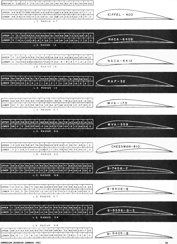
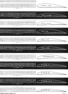
EIFFEL-400. Very popular among all modelers for some twenty years. Best suited
to rubber models.
NACA-6409. Another very popular section, usually associated with power models.
A fast efficient airfoil for rubber jobs.
NACA-6412. A good standard section for models operating under slow speed or high
lift conditions.
RAF-32. A well liked British section for large rubber models or gas. Has disadvantage
of a rather large center of pressure travel. But this has not affected its popularity.
MVA-173. A thin highly cambered section with good duration potential, if you
can handle the stability problems.
MVA-359. A calm air average performance of 2:30 on A-2 glider. Good in turbulent
air.
CHEESMAN-810. Mr. Cheesman designates this a laminar flow section. Briton John
Barker found its performance even better than the NACA-6409. That's right good!
B-7406-f. Benedek used this airfoil on the first Hungarian Wakefield to make
a consistent five minute average under the old rules.
BB-8306-b. Claimed to be good stable section with all 'round performance. Note
that a deep undercamber usually results in sensitivity in pitch axis.
BB-8356-b. Benedek set a record by being first Hungarian to make a 900 second
total under the 80 gram motor
rule.
B-6405-b. Airfoil used on Benedek's 1958 5th place winner at Cranfield World
Championships. Model showed excellent "prop-hanging" stability in very gusty weather.
Power Models:
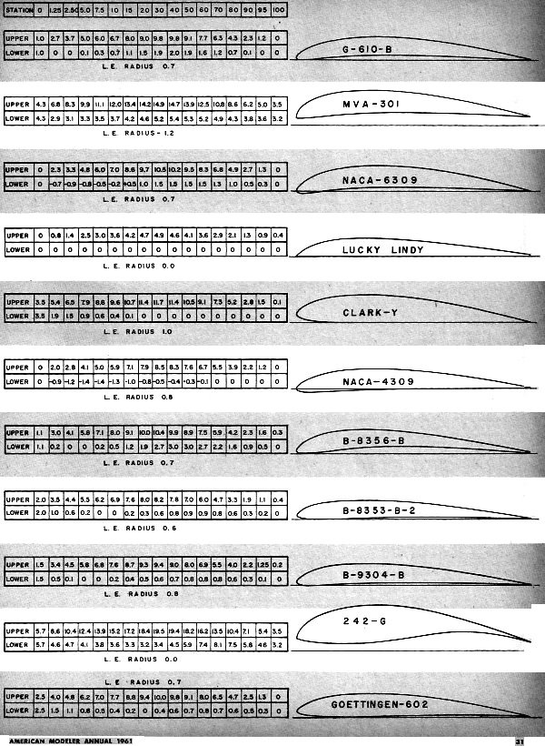
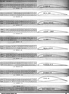
G-610-B. Carl Goldberg's famous wing section used on the Zipper and Sailplane,
etc. A very good airfoil.
MVA-301. Perhaps the best liked section from MVA. It gives excellent performance
in all ranges above a five inch chord. Note that I have drawn an almost pointed
entry on the L.E.
NACA-6309. Similar to the 6409 but with high point further forward.
LLUCKY LINDY. Standard section for all my FAI power models. Low drag. Has a better
glide than the shape would indicate. Must have turbulators for pitch stability.
CLARK-Y. Perhaps the best known airfoil in the world. It was developed by Col.
V. E. Clark in 1922. Its performance is not spectacular in anyone field, but it's
a good all-rounder.
NACA-4309. A section for faster models. Has small center of pressure movement,
which aids pitch stability.
B-8356-b. Designed originally for Wakefield and Nordic, this section shows good
potential for a low-rate-of sink power model.
B-8353-b-2. Designed specifically for the heavy weight FAI Power rules. A high
speed section.
B-9304-b. Another special airfoil for latest F AI Power rules.
2242-G. A Goettingen high 11ft section recommended by Dr. Lippisch for Clipper
Cargo, or any type requiring very high lift values. Notice the pointed leading edge,
similar to some bird wings. He emphasizes that the under surface of the wing must
be very . smooth on sections of this type.
GOElTINGEN-602. A good medium speed, low drag section.
You now have the basis for a scientific approach to model airfoil selection.
And you have the. method for reproducing any desired section, in any size.
Posted February 4, 2023
(updated from original post on 1/17/2013)
|