|
Prior to the
widespread use of mufflers on radio controlled model aircraft engines, exhaust
dampers were installed that worked in unison with the throttle. They were oblong or
butterfly-shaped flat pieces of metal that pivoted in the center and were connected
via a short pushrod to the carburetor's throttle arm. At full throttle, the damper
was straight up and down to block the exhaust port as little as possible. At idle,
the damper usually totally blocked off the exhaust port; of course some exhaust was
still able to exit or the engine would choke out and stop running. The first R/C
engines I used in the 1970's came with exhaust dampers. Part of its job was to create
back pressure in the combustion chamber, which caused the engine to run a bit hotter,
making a low idling speed more reliable.
See Part 1
Engine Idling Secrets
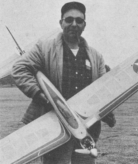
Researcher Harv at LIDS' meet.
Part Two by Harvey Thomasian
Now, to digress a bit we will discuss the needle valve and exhaust damper, returning
later to complete adjustment of the idle. This is done to give you a better idea of what
you are doing while you are doing it. In any event, if the addition of the exhaust damper
does stop your engine though it is fit correctly, work on the intake throttle but do
not change the needle valve setting. The needle valve does nowhere near the job of metering
fuel at low speeds as it does at high. As you can see, at high speed a relatively large
needle opening area is necessary to allow sufficient fuel to flow, but at low speeds,
because less fuel is necessary, the relatively large needle jet area is not required
and the fuel is just coasting - so this opening is not critical. Because of this, the
amount of fuel passed at idle is determined to a great extent by pressure differentials
(or call it suction) in the throttle barrel ... and we will prove this to you later on.
The main reason for the exhaust damper basically is to produce back pressure which
creates a slightly higher temperature along with restricting the flow of fuel and air
mixture. It also aids significantly in getting good acceleration. Beyond this, the theory
of the exhaust damper could become real confusing to most readers. Therefore I feel it
should be discussed in simple language rather than in theoretical values.
To get back to where we were on idle adjustment, the next step is where the boys and
men separate. With the damper connected, and the throttle adjusted, repeat the acceleration
and deceleration runs which were previously conducted without the damper. If all runs
well ... you are set ... leave it alone. However, the addition of the damper may bring
on another condition which requires another test. Here is the situation: the engine high
speed is good, idle is good, deceleration is good, but upon acceleration - somewhere
between idle and half throttle - your mill loads up and stops while large clouds of whitish
blue smoke pour from the stack. Engines that load up and stop on acceleration do so because
of an excessive rich mixture at idle, so get the file out again and work the V-notch
over a bit at a time until the engine accelerates well. During this, do not alter any
other adjustments unless necessary. About the only thing that might be necessary is to
readjust the idle speed stop screw. Watch the filing so as not to go too far to the other
side and lean the mixture.
A few paragraphs ago we declared that the needle setting is not particularly critical
at low speeds, and to prove it, you should be able to tweak the needle valve 1/2 turn
either way without appreciably affecting the tick-over. If, on turning the needle valve
out a bit, the engine loads up and stops, chances are the air bleed is not sufficient
and will require a slight file treatment at the V-notch. The opposite is true if the
engine leans when the valve is turned in.
Once you have arrived this far, you probably will be fairly well satisfied with performance
with one exception - there being a total lack of linearity in throttle response just
off idle, or to express it more simply, it is difficult to get a speed just a shade higher
than full idle. This can be done by sawing (with a Zona saw) a slot about 1/16" long
by 1/32" deep on. the lower side of the throttle barrel, opposite the V-notch. Keep this
slot 1/64" or less in width or you may have to rework the notch on the top side again.
The placement of the saw slot in the throttle barrel is illustrated in Dwg. # 5. This
is an old idea that appeared in American Modeler some years back and has recently been
resurrected by Harold deBolt and Howard McEntee.
There exist other factors outside what we have mentioned which can deter good high
and low speed. One of these is gum or varnish which is caused by storing castor oil for
long periods during which oxidization takes place resulting in gum formation on the piston
and sleeve when subjected to higher than normal operating temperatures. A check of your
engine in the following manner may show gum to be one of your problems.
Your engine which runs slow and hot at high speeds, even with cool fuel and plug,
will not run well at idle despite the fact that it ran well a while back. A very thorough
check shows nothing obviously out of kilter.
Gum or varnish which collects in the piston and wall may sometimes be not too evident
at casual observation, but may appear on close examination as a brownish color on the
piston of some engines. This messy substance (it almost looks glassy) puts such a drag
on the piston as to seriously curtail top performance and ruin good idling characteristics.
Your engine does not develop enough power to overcome it. To remedy this condition, remove
the piston and cylinder, place 'em in a bottle of acetone for a couple of days after
which both units should be thoroughly scoured with very fine household steel wool. The
steel wool will do no damage so long as you do not leave any in the engine at assembly.
If upon running you notice better operation, then you know gum or varnish was the culprit.
Another item that bears watching is the surgical tubing used in R/C stunt tanks, which
sometimes causes lean runs at high speed due to collapse of the tubing. Idle will eventually
sour up because the needle valve will be opened excessively to clear the lean condition.
Periodically, the tubing should be replaced to prevent this happening and simultaneously
check all fuel lines and filters for dirt, and that mysterious green stringy stuff which
clogs the needle valve.
Tanks with swiveling or tubing pick-ups, such as those ,made by deBolt and Veco have
proved best in R/C stunt work. We found that tank vertical positioning was not critical
in the engines tested, all performing well though the tank was lowered considerably.
If your new plane design appears more attractive with the tank centerline 1/4" below
the needle valve center, place it there as you will notice hardly any difference. We
found it best to place the tank outlet 1/4" to 3/4" below the needle valve. If tank height
is changed, check idle before flying. Also, when switching engine from a two wheel gear
airplane to one with trike gear, check idle as a change in ground angle alters the fuel
head which causes a greater or lesser flow at idle. Sharp bends in the line from the
tank to the engine may cause the engine to run weak or halt in violent maneuvers; bends
act as traps when the ship alters direction sharply. G-forces can hold fuel in a bend
and prevent its flow.
Make certain that the end of the tubing pickup is 1/8" to 1/4" off the tank bottom
when tank is held upright.
Lastly, keep your fuel lines short, with no loops.
Another item is vibration caused by poor mountings or by plastic props. Wood props
are excluded since we assume you balance them before flying, but plastic props, though
they be inherently static balanced at manufacture, have a tendency to vibrate being more
limber. This, along with poor engine mounting, may cause fuel foaming in the tank and
line which will hinder both high speed and idle running. To get around this you may resort
to packing around the tank with foam or rubber. When making an engine mount, make it
solid and put some mass around it to absorb vibration. Also, be certain that the engine
rests flat on its bearers - an engine tightened against distorted mounts tends to bind.
Many times we have seen a modeler take a new model out to the field with a spanking
new engine and have trouble with his top speed and idle because his powerplant hadn't
been run in. At both speeds his trouble is due to friction from snug fits, built in by
the manufacturer and meant to wear in. This treatment is cruel as engines tend to overheat
and freeze sometimes necessitating replacement of parts. Keep in mind that radio control
engines probably go through the severest conditions to which a model mill could be subjected;
much more so than U-control, free flight, or speed due to the fact that R/C flights are
sometimes 15 minutes long and under heavy load.
R/C engines are not running free at 17,000 to 18,000 R.P.M. Rather, they operate between
9,000 and 12,000 R.P.M. at the peak of the torque curve and highest mean effective pressure,
at which points, the loads are high. What we want to emphasize is that you must be certain
the plant is reasonably well broken in before flying.
Whenever we are asked about the need for fuel additives our answer is "not necessary
except possibly on cold winter days." We feel that fuel should be straight out of the
can from the hobby shop ... no diddling around. However, for those of you who must fool
around with additives to improve idle - and this is generally a cold weather problem
- use something which has a low flash point. Certainly this flash point has to be below
that of nitromethane. When our weather in New England drops below 20° F., we add
about an ounce of O.K. Cub diesel fuel per pint of glow fuel. The ether will assist both
starting and idling. Also, due to its high evaporative qualities, it is useful in conditions
where plug wetting is a problem. There are other additives which may be used to combat
specific conditions. However, their action is somewhat complex and not of interest to
most modelers.
Fuel blending is an involved art and should be approached by the average ftyer with
some trepidation unless he is prepared to spend long hours evaluating his results. Simply
throwing in an additive is not always the best solution for consistent results. Note
that some manufacturers are developing special fuels for R/C. We have had samples of
such fuel from K&B and Technical Model Products and find engines will idle 150 to
200 R.P.M. lower, and reliably.
We do not advocate hopping up (a practice of speed flyers) to increase power, as an
increase in horsepower does not always increase peak torque. Buy a bigger engine.
Some things not to do ... don't change engine timing, increase compression ratio,
bore out the throttle barrel (this will cause a sag under long, hard climbs), or file
the piston baffle (engine fuel consumption will increase).
Things you can do ... polish the intake passage in the crankshaft, bevel the bottom
bypass edge on the liner, lighten and smooth the connecting rod contour, smooth engine
interiors (clean out all die casting flash) and lighten the piston. This last step makes
the engine run a bit faster and with a little decrease in vibration level. Anything you
can remove from the crankpin side of the shaft will do the same. Some pistons are made
with an oval rib above the pin bosses to reduce out-of-roundness. This can be removed
to lighten the piston, but we do not guarantee longevity if this is done.
Recently we have been operating two large engines which were designed specifically
for radio control, the Veco-Lee 45 and the OS 49. That engine people have become seriously
interested in the R/C market is shown by these two products which are notable in their
rigid construction, long life, high torque in our R/C speed ranges, unusually low and
reliable idle, good acceleration and linear throttle response.
The Veco and OS are examples of more to come since other manufacturers have indicated
their intent to build fine R/C engines in all sizes. K&B has a 15 R/C and 35 R/C
in development stages with a yet larger engine on the drawing board.
We gratefully acknowledge the assistance the following individuals and companies gave
in the preparation of this article: K&B Mfg. Co.; World Engines; Technical Model
Products Co.; Veco Products Corporation; Harold deBolt; Lee Renaud.
Articles About Engines and Motors for Model Airplanes, Boats, and Cars:
Posted March 4, 2018
|