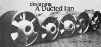
|
For
many years it has not been necessary to design and build your own
ducted fan unit. The market is chock full of computer optimized
designs for both internal combustion engines and electric motors,
using some of the most advanced materials for construction. However,
there was a time just a few decades ago that ducted fans were the
purview of a few talented and motivated do-it-yourselfers that help
to advance the state of the art to where it is today. This article,
extracted from the February 1971 edition of American Aircraft Modeler,
is one of the earlier treatises on the subject.
 By Wallace A. Kulczyk By Wallace A. Kulczyk To be useful, these piston-driven
air pumps require careful design, testing, and adjusting.
THE ADVENT OF THE JET airplane presented a
serious challenge to the scale modeler. How could it be duplicated
in model form? Obviously, hanging a model engine/propeller combination
on the nose of a scale model jet airplane will make it fly, but
it certainly detracts from the appearance and defeats the intent
of scale modeling, i.e. to duplicate, to the maximum extent possible,
the features of the full-size airplane. Model jet engines, at least
those that are presently available to the average builder, are terribly
noisy, generate fantastic amounts of heat and, in general, are hard
to handle. The ducted fan propulsion system has evolved as a result
of the requirement to simulate jet propulsion in a model aircraft.
Simply stated, the ducted fan system generates thrust by
accelerating an air mass and ejecting it through a simple nozzle.
Power is applied to the air mass by means of a multi-bladed fan
rotating in a duct or shroud which fits closely around the fan.
Fan efficiency is improved by the close shrouding of the fan which
reduces airflow losses around the tips of the fan blades. The ducted
fan is in essence an "air pump." Studying available data
on existing ducted fan designs has led to several conclusions:
(1) Poor Maintainability: In almost every case, the engine
and fan combination is built into the airplane during the early
stages of construction and, thus, is essentially inaccessible for
normal maintenance, cleaning, or servicing thereafter. (2)
No Performance Guarantee: The builder has no way of knowing, until
after the model is built, that the proposed engine/fan combination
will provide the required thrust. (3) Non-Interchangeability
of Parts: If more thrust/power is required (see item 2), the builder
is forced to disassemble the model, to some extent, in order to
replace the engine (see item 1). In addition, the power unit is
not easily interchangeable between models. (4) Improvement
Required in Fan Design and Construction: Sheet metal fans are frightening!
A blade failure at 15,000 rpm plus, can be disastrous to the operator,
the model or a spectator. Proper shrouding helps but sheet metal
exposed to vibration is notorious for developing fatigue cracks.
Evaluation of the above deficiencies resulted in the development
of the ducted fan power package presented here. We have attempted
to eliminate the disadvantages and difficulties encountered in ducted
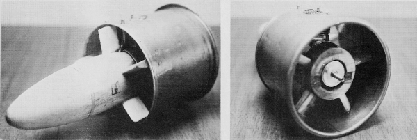
fan construction. The power package is constructed using a metal
can or appropriate tube as the basic unit. Plywood "spiders" support
the engine in the center of the can. These supports also form the
basic frame for the airflow straighteners which are essential for
good performance. The fuel tank is mounted behind the engine and
is faired in by using balsa block.
Rear of five-in. unit shows streamlined,
fuel-proofed rank fairing. Leading edge of flow straighteners
is opposite fan blade angle.
 The entire engine/fuel tank/flow straightener assembly is
assembled as a complete unit prior to installation in the can (see
sketches). The power package can be mounted on a test block and
thrust-checked by using a cardboard tailpipe of the same dimensions
as those to be used in the model. When the thrust output has been
verified, the model can be designed around the dimensions of the
power unit, with reasonable assurance of good performance.
The first step is to determine the fan diameter. Regardless
of the size desired, the same basic design procedure will apply.
Experience has shown that fans of less than four-in. diameter do
not produce sufficient thrust for anything except a lightweight
free flight model.
Extensive testing indicates that a six-bladed fan with a
hub diameter 50% of the fan diameter performs exceptionally well.
The blades are mounted on the hub at a 45-degree angle to the plane
of rotation. The blade chord should be such that the sum of the
chords of the six blades at the hub does not exceed the circumference
of the hub. However, this generally provides a blade with a chord
wider than necessary for the rpm's at which models will be operating.
The fan would be excessively loaded, therefore, 75% of the figure
obtained above works well for blade chord. Two methods of
fan construction are shown. The first method, which uses plywood
blades pinned into slots in a laminated plywood hub, requires the
builder to carefully carve the twist into the blades. Twelve to
fifteen degrees twist, resulting in a blade tip angle of 30 to 33
degrees, is desired. The amount of twist available will depend on
the thickness of the blade material.
The
second method, stacking the fan profiles, permits the builder to
easily obtain the desired twist angle. Either method requires careful
but not difficult work. "Resorcinal" glue is used to fabricate the
fans regardless of which method is used. Aluminum fans have been
constructed using a turned-aluminum, slotted hub with pinned sheet
aluminum blades, but their weight far exceeded any expected thrust
increases. The extended fan hub is simply a turned balsa block affixed
to the basic fan assembly. Do not delete the hub since it helps
to establish airflow into the fan blades-especially at the root
of the blade. The engine mount is designed around the dimensions
of the engine. Having determined the distance from the front face
of the thrust washer to the rear of he crankcase (assuming a front
rotary valve engine), and the width between the engine bearers,
some basic design considerations can be made. The dimension from
the face of the thrust washer to the cylinder centerline also must
be determined. Plot these measurements into a full-scale profile
and front view of the can to be used. Superimpose the diameter of
the hub on the front view and locate the engine bearer cutouts.
Plot the "spider" legs (live for a six-bladed fan) at least ¼" wide,
⅜" for a five-in. or larger unit. The legs are spaced 72 degrees
apart, the top center leg of the rear spider being located behind
the engine cylinder. The location of the forward spider should allow
for a curved leading edge to be installed as a lead in to the flow
straighteners. Fore and aft location of the engine mount in the
can will be determined by (Sorry for the inconvenience,
but this paga of the scan is missing - it will be added soon)
four-in. fan - beef stew.) Examine the can carefully for
dents or other defects. Buy the stew and heat and eat the contents
or throw them away. Carefully remove the top and bottom of the can
so that the stiffener rings (ends) are not deformed.

If a fan larger than four-in. is required and a suitable can is
not available, several alternate solutions are possible. Rolled
1/16" sheet aluminum with the seam welded and then filed away or
a plywood "can" as shown in the sketches will do the job nicely.
The can is the heart of the unit and extra care in the fabrication
of this item will pay dividends later on. The first step
in method number one is cutting several disks from plywood, then
laminating them to provide a hub of the required thickness. After
the glue has set, chuck the hub in a ¼" electric drill and with
a wood rasp or sanding block true up the assembly. Next mark the
hub for the blade slots. Make up a template to insure that all slots
are exactly the same angle on the hub. Plan to make the slots deep
enough so that after the blades have been inserted, the hub and
blades can be drilled for ⅛" or larger dowel pins. These pins are
insurance that the blades will not separate from the hub at high
rpm's. After the assembly has been glued up and is thoroughly
set, file, carve and sand the airfoil into the blades as shown.
Keep leading and trailing edges sharp and the back side of the blade
flat. A simple convex shape to the front face of the blade will
do nicely. Method number two for fan construction involves
stacking up a series of plywood profiles to the desired hub thickness.
Stagger each successive profile until the required root and tip
angles are obtained. The proportions shown in the sketches should
establish the width of the blade elements adequately to insure that
sufficient material is available to obtain the required air foil
Note that this method provides a blade which has a wider chord at
the tip than at the root. However, with the more effective twist
obtained, the blade tip angle is more favorable and the increased
chord should be handled easily. The fan must be carefully
and critically balanced, and must run as true as possible. Balance
may be achieved by drilling holes into the back of the hub, but
don't get carried away. Do not establish the final fan diameter
until ready to mount the engine assembly in the can. The closest
possible running fit is most desirable. Properly constructed, the
fan will be close to perfect balance to begin with. An extra coat
of clear dope on one or two blades may do the trick.
Engine Mount The engine mount consists
of a forward and aft plywood spider (¼" or thicker) and a pair of
hardwood engine bearers. Saw out the spiders, leaving their legs
slightly longer than required. Slip them over the engine bearers
with the engine on the rails so that any trimming requirement for
engine clearance can be determined. Once the correct positions of
the components have been established, mark, drill for dowel pins
and engine mounting bolts and epoxy the whole assembly together,
with the engine in place. Fuel-proof all interior surfaces of the
mount assembly and make certain the engine mount bolts will not
loosen under vibration. Trim the ends of the spider legs for a slip
fit into the can. The engine crankshaft must be centered. It may
be necessary to remove the cylinder head. Small balsa blocks or
curved sheet balsa panels are used to fair the engine into the center
body of the mount. Cut a hole under the engine to vent off crankcase
heat and excess fuel or oil spillage. Don't forget fuel-line access
holes. Having faired the center body, next cut inserts from
balsa of appropriate thickness to fit between the forward and aft
spider legs and up against the center body. Build up a curved leading
edge on the forward spiders to form an angle of approximately 20
degrees to the chord of the flow straightener and opposite the direction
of fan rotation. These serve as lead-ins for the rotating airflow
leaving the fan. The desired 20-degree angle should be available
at the outboard end of the straightener and may be reduced closer
to the center body, If the size or construction of the unit cannot
provide this curved leading edge, simply round off the leading edge
of the spider leg, favoring the direction of the rotating airflow
off the fan. The aft spider legs are faired by using trailing
edge stock of appropriate thickness - ¼" or ⅜". Install, keeping
the 90-degree edge on the side of the flow straightener which meets
the rotating fan airflow. Observed in cross section, the flow straightener
should look like a crude air foil. Fairing the fuel tank
is up to the individual. A little study will reveal the best method
to adequately fair in the tank and provide a smooth transition for
the fan airflow. Fuel-proof the entire engine mount assembly
and it is ready to be installed in the can.
ASSEMBLY Cut holes in the can as required for the
cylinder head and needle valve extension. Fuel-tank fill and vent
lines should also pass through to the outside of the can. With the
fan trimmed and mounted on the engine, slide the engine mount assembly
into the can, lining up the hole for the cylinder head. br>
Make a shim of a strip of poster paper and encircle the ends of
the fan blades, centering the fan in the can. Use as many thicknesses
as required to insure that the fan will be centered. Now, working
from the aft end of the can, check for any shims which may be required
between the flow straighteners and the inside of the can.
Install the cylinder head on the engine. When satisfied with
the location of all components, "paint" the assembly into the can
with epoxy thinned with a few drops of dope thinner. Very smooth
fillets should result and the thinned epoxy has excellent penetration.
Let the unit set over night, pull out the fan shim, check free rotation.
When the power package is completed, verify its performance.
From scrap shelf stock, available at most lumberyards, build a thrust
mount as shown. The two forward mounts support the can assembly
and the rear mount supports the tailpipe. Make a tailpipe of light
poster paper which fits snugly over the aft end of the can, and
which has an exhaust area of 75% of the effective fan area. Effective
fan area is defined as the total area based on fan diameter minus
hub frontal area. The thrust mount may be mounted on wheels,
rollers or in a swinging parallelogram to provide as friction-free
an assembly as possible. Run the unit, tying the thrust mount to
a small spring scale to measure the thrust. Slice sections from
the tailpipe, gradually opening up the exhaust area and thrust check
the unit after each adjustment. Use the tailpipe area which generates
maximum thrust for the particular fan/ engine combination being
used. The ducted fan power package described here was conceived
as being interchangeable between several models and suitable for
free flight, control line and radio control use. The installation
of the unit in the model requires only that the aft edge of the
can be a snug slip fit into the forward end of the tailpipe, with
the forward portion of the can resting in a suitable cradle, held
down by a simple strap or lugs. Selection or design of a
model to use this type of propulsion should take the following features
into consideration: (1) Reasonable wing area for the size
of the aircraft (MIG-21 or F-104 - maybe, U-2 - no question).
(2) Reasonably sized tailpipe exit. For scale designs, those
aircraft with afterburning engines will provide adequate exhaust
area in proportion to the size fan installed. Example: F-100 - good;
T-33 - aft fuselage would need modification for tailpipe.
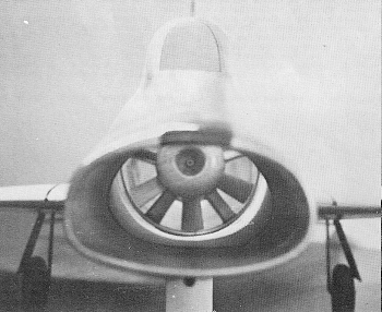
(3) Inlet areas should be at least equal to the effective fan
area. Some minor considerations to scale are acceptable and, if
necessary, auxiliary air inlets can be provided. Example: MIG-15
- adequate as is; F-100 - too small, requires auxiliary inlet.
(4) Thrust to weight ratio -1:2 or better is desirable.
One of my models has a 1:3 ratio and flies well (6-lb. aircraft
- 2-1b. thrust). The ability to thrust-check unit provides weight
target. Recommended Engine/Fan Size Fan Diameter
Engine Size
3"
049-099 3½"
074-15 4"
15-29 4½"
23-35 5"
29-45 5½"
40-60 6"
51-up Pressure fuel systems work well and provide consistent
operation, but are not necessary, Throttle systems also work well
but either an exhaust baffle or intake throttle only is required
since very low rpms are not necessary to effectively reduce thrust.
Articles About Engines and Motors for Model Airplanes, Boats, and Cars:
Posted September 28, 2013
|