|
The Lockheed
C-130 has long been my favorite post-World War II four-engine airplane, and I have vowed to someday build a control
line model of it. This construction article from a 1956 issue of Young Men magazine might provide just the impetus
needed to start the process since it includes highly detailed plans and assembly drawings. Lockheed toolmaker Henry 'Hank'
Edwards designed and built the original model using first two .19 engines and then converting to four .09 engines. My model,
if it ever becomes a reality, will use four brushless electric motors. Unfortunately, because of the way the pages
with the plans and assembly drawing were bound in the magazine, there is a missing section in the middle of both. I left
what seems to be the appropriate spacing between the two halves, so if you print out the plans full size, you should be
able to sketch in the missing details well enough to build the model.
Many thanks to Bob Balsie for sending me scanned pages to process and post!
This Spectacular Lockheed "Hercules" Model Performs on One Engine!
By Henry G. Edwards with Paul Del Gatto
Take your choice: two .19-size powerplants or four .09's; but either way you'll have the most publicized model in your
town!
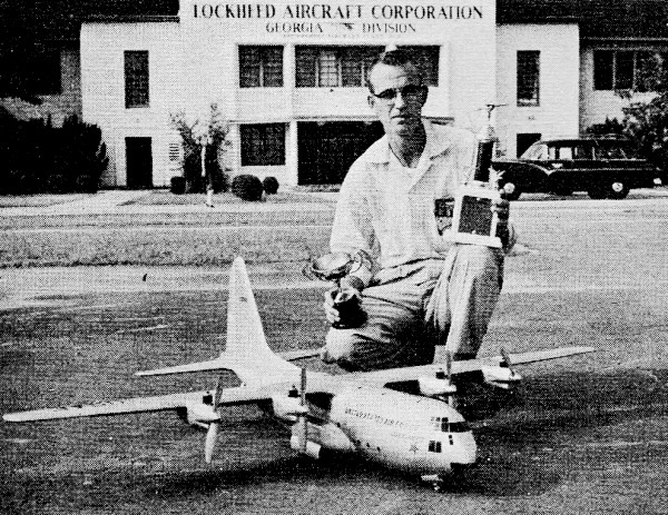
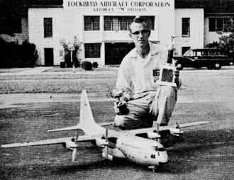 Hank is Lockheed tool inspector; this is his 1st flying model Hank is Lockheed tool inspector; this is his 1st flying model
Being a Lockheed employee I was naturally quite close to this particular aircraft; the more I saw of the Hercules C-130
the more convinced I was that I wanted it to be my first multi-engine project. Its gargantuan proportions impressed me.
But it went deeper than that, for incorporated into the design were many features which justified its, being called the
"freighter of the future." One of its unusual features is the low-slung fuselage incorporating a floor that. is the same
height as truck beds. Upswept tail arrangement is utilized to accommodate rear-end loading.
Flight tests have indicated that the speed of Hercules will surpass that of our present luxury airliners; the C-130 can
land on an 800 ft. runway. Considering that fully loaded the Hercules weighs in at about 54 tons (of which about 20 tons
are cargo) arid it has a 132 ft. wingspan, "impressive" is the right word.
There's a total of 15,000 horsepower behind the 4 turboprops. Unusual is the use of deeper camber for the bottom of the
stabilizer than for the top. Maybe the engineers who thought up this feature were old "Pacer" addicts.
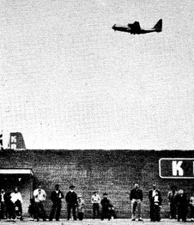
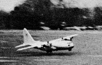
Single-engine performance is eye-raiser!
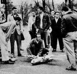
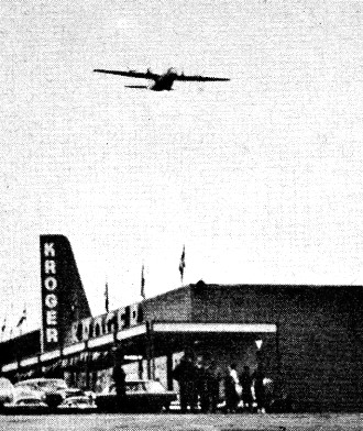
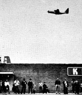
Crowd pops up when C·130 appears.
Hercules model performs on single .19 in front of Lockheed's Marietta, Georgia, plant.
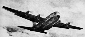
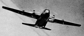
Four Allison T-56 turbine engines in slim nacelles power "freighter of the future."
Stable flight is majestic thing indeed.
Photos from Lockheed's "Southern Star."
(Model bugs new to the hobby may not have heard about Sal Taibi's free-flight "Pacer" design which. incorporated an inverted
stab and was one of the hottest designs of the early '40's. It's still a strong favorite with many old-timers and it still
brings home the bacon at contests.)
But getting back to "Hercules" and control-line models in general: Nothing can hold a candle to a multi-engine model,
particularly if it is a scale replica.
Certainly you can't build this multi-engine model overnight or even over a weekend. What we prefer is the kind of project
that can really be called model building. Ask anybody who has tried multi-engine designs, when it comes to flying there's
nothing that can challenge the roar of two or more engines in synchronization; or that breathtaking moment when the model
is released and it accelerates for a take-off.
If this is your first multi-engine design we suggest you install two engines operating on the inboard nacelles; leave
the engines off on the outboard nacelles. Two K. & B. 19's proved more than ample power for us and the model even performed
on one!
We have gained sufficient confidence to convert over to four .09's and performance has been to everyone's satisfaction.
What has improved still more is our ground operations prior to each flight. We've gotten so we look like centipedes-on-the-double.
If you're an old hand at multi-engines, you might decide on the four .09's to begin with.
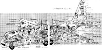
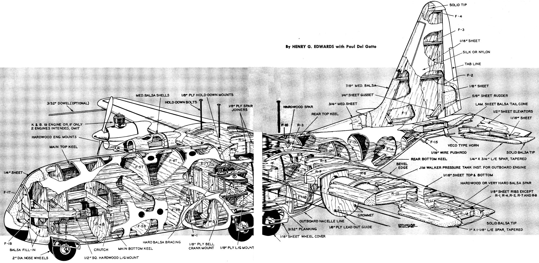
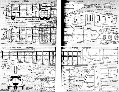
Lockheed C-130 Detailed Assembly Drawing by Douglas Rolfe
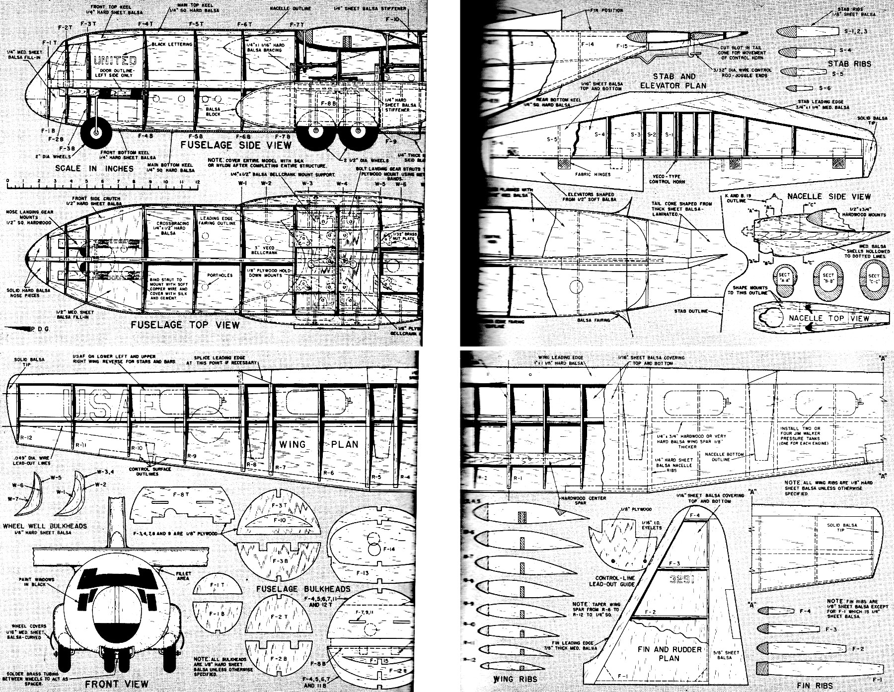
Construction
With this project it is advisable to begin construction with the wings and tail surfaces, for then things will be easier
in the final assembly. The wing, stab and fin ribs are cut from hard sheet balsa. In all probability most of the wood lengths
you'll be using for the wing loading edge and spar will be 3 feet, and so will require splicing. Wing spar can be spliced
in the center since plywood stiffeners are used, However, for the wing leading edge, splicing is recommended as indicated
at the outboard engine nacelles.
Do not shape the leading edge of the wing at the center section until final assembly.
Before planking the wing install Jim Walker pressure tanks; two or four tanks will be required depending of course on
whether you plan to use two or four en-gines. Mount all the tanks with the fuel outlet facing the outside of. the flight
circle.
Plywood control-line wing guide should be recessed into the wing structure and cemented securely before planking.
Frame structure of the wing and tail surfaces are covered with 1/16" medium sheet balsa. Elevators are shaped from 1/2"
soft sheet balsa and linked together by a Veco-type horn. Rudder, offset 1/2" off centerline, is shaped from 5/8" soft sheet
balsa. The dorsal can be built up from laminated balsa such as that required for the stab leading edge.
Nacelle construction is quite simple, consisting primarily of an upper and lower shell with hardwood engine mounts shaped
to the nacelle contour and cemented between them. The desired cross-section and accurate fitting to the airfoil curvature
may be a little ticklish - but "Plastic Wood" around the exposed area will give that professional touch.
Get the fuselage started by cutting out all formers, some of which are 1/8" plywood and the remainder 1/8" very hard
sheet balsa. Lay down the basic crutch and cement to it several of the key top formers so that the top keel can be added
before removing from plan. After the crutch has been removed from the plan fill in these areas with sheet balsa where the
landing gear assemblies are to be installed.
Bend nose gear to shape; it is bound with soft copper wire to 1/2" square hardwood mounts and spot soldered, Then cover
the entire unit with heavy silk and cement it thoroughly.
Main gear is bent to shape and belted to a 1/8" plywood mount with the aid of metal bands. Mount is full width of fuselage
except for planking; it fits between formers 7 and 9. When entire unit is completed cement it to the crutch and the sheet
balsa bracing.
At this point install bellcrank assembly with exception of pushrod. When completed, cement all these fuselage bulkheads
in place that are keyed to the crutch assembly. Add the bottom keel and the last two formers.
We would recommend planking the fuselage with 3/32" x 1/2" medium balsa strips except around sharply curved sections
of the fuselage where you can avoid steam-bending the wood by using a softer grade. Begin planking along the crutch until
the rear formers are sufficiently rigid to hold the stabilizer.
The tail cone is blanked out from soft sheet balsa and shaped to blend in with former 15 and the stab and elevator assembly.
When completed, cement the tail cone to former 15.
Additional construction details will be found on the full-size plans.
Full-size plans for the C-130 Hercules (by Paul Del Gatto) are on Group Plan #656 from Hobby Helpers,
770 Hunts Point Ave., New York 59, N.Y. (50c).
Posted April 23, 2016
|