|
A grid dip meter (aka a grid dip oscillator,
dipper, or dipmeter) has long been the instrument of choice
for fine tuning LC-tuned receivers for maximum sensitivity at a
particular frequency. It is a simple device that oscillates at a
predetermined frequency and has a meter in the grid bias circuit
to measure current. When the grid dip meter tuning circuit's inductor
is in close proximity to an external inductor-capacitor tank circuit
that is tuned to the 'dipper's' output frequency, the grid current
exhibits a significant reduction in value - hence the name grid
dip meter. Modern versions no longer use vacuum tubes that have
screen grids, but the name persists even with the use of transistors
that, for BJTs, have a base junction and FETs, that have a gate,
instead of a grid.
 Heathkit
made a very popular grid dip meter that can still be found on eBay
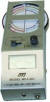
and some amateur radio swap meets. MJF Enterprises, one of the largest
modern manufacturers of Ham test equipment and rigging, makes the
MFJ-201, 1.5-250 MHz Dip Meter that sells for about $150. Heathkit
made a very popular grid dip meter that can still be found on eBay
and some amateur radio swap meets. MJF Enterprises, one of the largest
modern manufacturers of Ham test equipment and rigging, makes the
MFJ-201, 1.5-250 MHz Dip Meter that sells for about $150.
Thanks to Bob Balsie for scanning the
pages.
Meet the Grid Dipper... the Best Friend a Radio Control Fan
Ever Had
Never heard of this device? You might call it a low-power transmitter;
invaluable for fast field checks.
By Howard G. McEntee
Let's say you've just finished a new receiver that you designed
yourself. When you hook it up to the batteries and turn on the juice
everything seems O.K. (no bright flashes or smoke, at least!) but
you can't get any reaction from it when you key your transmitter.
After a goodly bit of fussing you figure maybe the receiver won't
tune to the transmitter; should you add turns to the coil or take
some off? Or put a higher or lower condenser across the coil? Maybe
you are using a surplus slug-type coil form - it looks about the
right size, but what kind of a core does it have?
Grid Dip Meter
All these questions could have been answered in a moment, and
you would have the answers before you even turned the receiver on!
If you had a Grid Dipper, that is. Well, what's a Dipper?
It is simply a very low powered "transmitter" with a calibrated
dial and a milliameter in a special location in the circuit. Take
a look at Drawing 1, which shows the Dipper which will be described
here. You will note a tuned circuit at the left-hand side - consisting
of coil L1 and double-section variable condenser C1. Next we come
to the old reliable 1AG4 tube, which gets its power from A and B
batteries.
The meter M is not in the plate circuit where we normally find
a meter in both transmitters and receivers, though. Before we go
into why there is a transistor needed, we should say that the grid
meter in most Dippers is connected into the circuit in place of
resistor R2. It measures grid current of the tube, and gives a great
deal more sensitive indication - for the purposes of this type of
instrument - than would a meter in the plate circuit. When the coil
L1 is brought near another coil tuned to the same frequency, the
grid current meter will show a sharp drop in current, hence the
name Grid Dipper. Incidentally, don't expect to get the same results
from a meter in the plate circuit; the plate current changes very
little at any time.
There are many Dippers on the market, some of very high quality
and priced at several hundred dollars. You can also get a kit for
a very good one at around twenty dollars. All these units, however,
work on the power line. We feel this instrument has so many uses
in R/C that it should be battery-powered, so that it can be taken
to the flying field, as part of your regular "tool" kit. For, next
to the meters that enable you to check operation of your equipment,
a Dipper is certainly the most handy instrument you could own.
We wanted to keep the battery power down, so life would be high;
this meant use of a low-drain tube, and the 1AG4 does a fine job.
However, grid current of this tube, with a 45 V. B battery, is only
around 0.2 ma. or less. A 200 microampere meter will do a good job
in this unit, but such meters are expensive and delicate, so we
chose the easy way out. A cheap transistor is used as a current
booster, enabling use of any meter up to a 5 ma. job. The meter
in the unit shown is actually a 500 microampere surplus job, chosen
simply because the cost was fairly low, and it was small in size.
To protect this meter from shook and from incorrect setting of R2,
we shunted a resistor R5 across the meter, making it equivalent
to about a 1112 ma. job. The meter you pick doesn't need any particular
dial calibrations, either, since all readings are simply comparative
- they don't mean a thing in precise units.
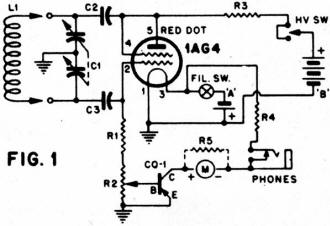
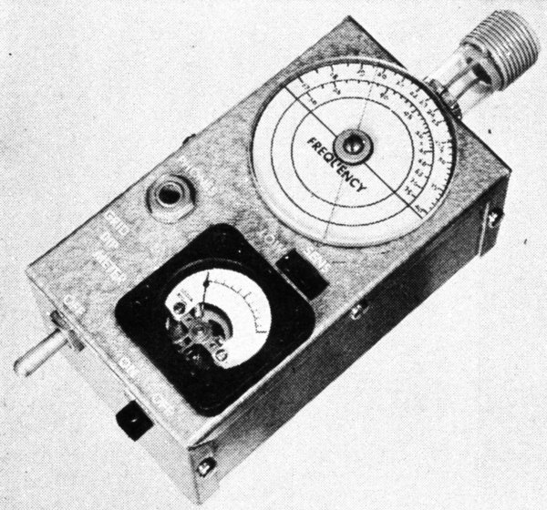
Fig. 1 - Grid dip meter schematic
A dual-section tuning condenser is used to eliminate hand capacity
when tuning. The condenser used here is a very compact type designed
originally for transistor broadcast receivers - though our version
has two sections of the same capacity. It has a stub shaft tapped
for a 4-40 screw. Instead of a knob and dial, we have fitted just
a 2-1/2" diameter plastic disc; a line scratched across the underside
of the disc is used as the indicator, and the disc itself is the
"knob." The Dipper is normally held in one hand with the thumb on
the edge of the disc, giving a sort of vernier tuning action.
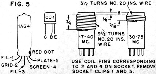
Coils have been made to cover a continuous tuning range from
17 to 75 mc., thus taking in both the 2714 and 50 mc. frequencies.
The oscillator will go a bit higher - perhaps up to 100 mc. or so;
if you want it higher, redesign of the tuned circuit is required.
It will also go lots lower in frequency, if you want to make another
coil.
The unit also works as a sensitive field strength meter. There is
no provision for an antenna, so you will have to set it quite close
to the transmitter, but by turning R2 away from the ground end,
you can get a much higher meter reading. In this case, of course,
you leave the HV switch open (filament on) and the tube acts as
a diode, with the transistor boosting the current produced. The
meter will read low, but will go up when you turn the transmitter
on. For checking tone transmitters, plug phones into the jack, with
the HV switch open. Again, the transistor will give a big boost
to the signals, over what you would get without it; set R2 for the
loudest indication in the phones.
Practically any PNP transistor you can get hold of will be adequate
for this purpose; at this writing, there are supposed to be some
reliable makes on sale at less than a dollar. We were not able to
get hold of one for test, but they would undoubtedly be O.K.; simply
be sure you use a PNP unit, not an NPN. Power for the transistor
comes from the filament battery of the tube, and the plus end of
this battery must be to ground.
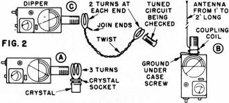
Fig. 2 - Optional antenna and coupled wire connection.
Since sub-miniature parts were used throughout, we could see
no sense in producing a big bulky Dipper, but if such a compact
unit scares you, there is no reason why it can't be made as large
as you want. Just try to keep the tuned circuit parts in the same
general arrangement, and keep other parts away from them as much
as possible.
Construction starts with hacking all the needed holes in the
standard aluminum box. Everything is mounted on the top - the part
that fits outside of the other - except the B battery. Our R2 is
of the type used with gas tube receivers and came with a knob attached;
it is therefore mounted vertically, with just a small edge of the
knob above the panel. An aluminum bracket holds it.
The condenser C1 is held flat against toe underside of the top
panel with 4-40 flat head screws, and to it is attached a little
Bakelite plate holding the tube socket together with R1 and R3.
These parts, also C2 and C3 are "hot" - that is, there is RF on
them and they should not be placed flat on the metal case or condenser
frame. Two more 4-40 FH screws hold the plate to C1, and the whole
assembly of C1, C2, C3, RI, R3 and the tube socket are wired up
before fastening them into the case. Leave leads from C1 terminals
long enough to run to the coil socket. Be sure to place a ground
lug under the Bakelite plate before you fasten it to C1, and connect
this ground to the others in the unit.
The phone jack must be insulated from the case by means of two
washers, so make the hole for it large enough. The HV switch we
used is a SPDT type which has a snap action to one side - that is,
you can push it over but it won't stay - and a "hold" position on
the other. The central position of the lever is off. As it comes,
this switch takes a lot of pressure to work it, so the lugs holding
the switch together were pried up and the insulated bottom section
removed. A single coil spring that runs up into the lever was clipped
shorter until the action on both sides of center is positive but
quite light, then the switch was crimped shut again.
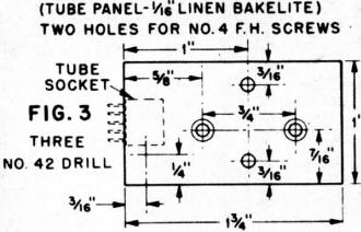
Fig. 3 - Dip Meter tube panel dimensions.
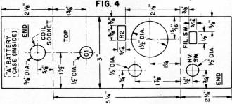
Fig. 4 - Dip Meter chassis dimensions.
Since it will never need replacing (the tube might, or you might
want to swipe it for some other use) there is no use providing a
socket for the transistor. It is just soldered right into the circuit.
However, don't clip the leads short. Leave them about as they come,
and be sure to hold each lead with a pair of long nose pliers right
at the base of the transistor, as you solder it in. Too much heat
on these leads can ruin this unit. In our Dipper, it can be seen
nestling against the underside of the meter.
B batteries were chosen for maximum life consistent with what
we could fit into the case. For the A battery, this called for a
mercury cell, which is exactly the size of a pencell; a pencell
- either regular or hearing aid type - will work fine, but won't
approach the mercury cell in number of hours of use you can expect.
The 502 cell specified will give a life of about 60 hours, and you
can squeeze a size 12 mercury cell in the same holder with a bit
of re-bending, and get some 90 hours from it. The B battery, is
good for two or three hundred hours of use; an aluminum strap holds
this battery in the bottom of the case.
When the Dipper has been assembled and wired, insert the tube,
turn R2 to the ground end and turn on the filament and plate switches.
Now move R2 slowly and the meter should start rising. R2 is usually
set so the meter needle is at about three-quarters full scale. You
can check the B current of the tube if you wish; it should be about
2 ma. You will find that the meter shows a slight variation as C1
is rotated through its full range; in our case it is highest at
about 1/2 of full capacity on C1, dropping a bit at maximum and
minimum capacity.
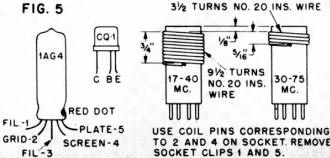
Fig. 5 - Grid Dip Meter vacuum tube lead identification
and pickup coil details.
Also, readings will be higher over the entire range with the
low frequency coil than they are with the high; you just set R2
to get the meter reading you want.
Now, what about calibration? This poses a real problem, unless
you know someone who has a working Dipper, or a frequency meter.
This Dipper can be calibrated quickly on signal generators used
by radio or TV servicemen. In our case a small but fairly accurate
calibrated field strength meter was used. Holes were bored through
the plastic disc over the arcs where the calibrations for the two
coils would go. Then the Dipper was fired up and the dial rotated
from end to end, marking the main dial readings with a pin stuck
through the holes (made with a no. 60 drill) in the disc. The disc
was then removed and the markings made lightly with a pencil, to
be sure they were correct, then finally they were gone over with
India ink.
_small.jpg)
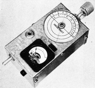
Internal construction view.
If you have no way of making a calibration, you still can have
a very useful instrument that will show you where 27-1/4 mc. is
- you just mark this spot with an R/C crystal. Connect two or three
turns of insulated wire to a crystal socket as in Dwg. 2a, plug
the crystal in, and hold the coil close to the Dipper coil. Then
start with C1 at maximum capacity and turn it slowly toward minimum.
When you reach the crystal frequency you will get a sharp dip of
the meter at approximately 27-1/4 mc. We say "approximately," since
the frequency is a bit different than it is with the crystal working
in a transmitter; actually, since the Dipper calibration is a bit
coarse at best, you can call that spot on the dial 27-1/4 mc. Incidentally,
a crystal that won't give this indication with a Dipper is pretty
weak or altogether defective.
We've mentioned use of the Dipper as a field strength meter;
much greater sensitivity can be had by use of a few feet of antenna
the lower end of which is wrapped a turn or so around the coil and
the grounded to one of the screws on the case. See Dwg. 2b. Proximity
of the coupling turns to the coil will shift the tuning, of course,
but a few checks without the antenna will show if you are on frequency,
before you add the antenna and coupling arrangement.
The Dipper is a low-powered transmitter, of course, and may be
used to check receivers for sensitivity - receiver operation at
so many feet away shows what you can expect with a regular transmitter.
This will take a bit of playing before you learn what to expect,
but with experience you can tell pretty much what a receiver will
do, without even taking it out of the shop. But WARNING: don't turn
the Dipper on at the field while someone else is flying!
When checking a tuned circuit, hold the Dipper close to it till
you have located the frequency, then back off till you have just
a readable dip of the needle; this gives a much more accurate check
of frequency. If you can't get L1 near enough to the coil you want
to check, to get a decent meter reading, you can use a "link" to
couple the two. Drawing 2c shows the idea; use any sort of insulated
wire for the link. You can check a tuned transmitter antenna, either
by holding the Dipper coil close to the antenna itself, or near
the coupling coil of the transmitter. In either case it is wise
to remove the crystal from the transmitter, as it can give a false
indication of resonance.
Well, there's the Grid Dipper - and it can do a great many more
things than we have covered. You'll find a lot more uses for it
yourself, and after you have used it awhile, you'll wonder how you
ever got along without it!
Grid Dipper Parts List
Posted October 25, 2015
|


.jpg)