|
If you have been searching for a project to build and fly that will generate a "ululating whine," then the Spinning
Disc Saucer is the model for you. Measuring 38" from tip to tip, this ½A powered alien craft uses a unique
configuration with the engine mounted on a outboard pod and a counterweight on the opposite side to generate the rotation
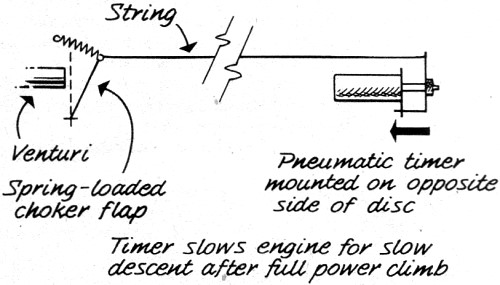
- which causes the Doppler effect that creates the weird sound. Mr. Clough designed a timer device that slows the
engine after a preset period to bring the Spinning Disc Saucer down under power rather than allowing to fall like
a side-to-side-swooping falling leaf. This would make an interesting adaptation to electric power with a micro
radio system for throttle and possibly pitch control.
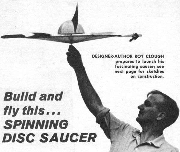
Build and Fly This ... Spinning Disc Saucer
|

Designer-Author Roy Clough prepares to launch his fascinating saucer; see next page for sketches on construction.
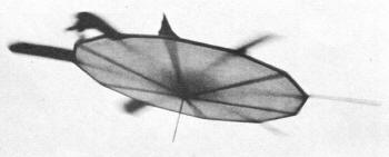
Spinning Disc Saucer in flight.
|
It floats up weirdly with a peculiar ululating whine reminiscent of a flying saucer from a science-fiction movie.
Then, moving through the air graceful as a gull it begins its descent and returns to earth gently as a feather.
This novel model project is sure to stop the show at any flying site. Best of all it is easy to build, certain
to give good results and it is probably the only model you'll ever construct that will fly right off the board with
no adjustment whatsoever.
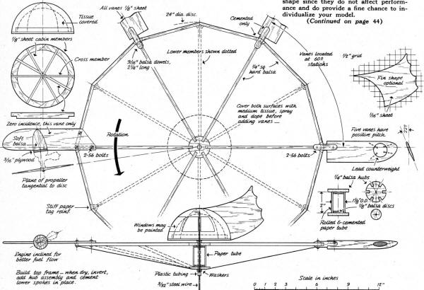
Begin by sketching out the 2 foot 12-sided disc on insulating board. Cover with waxed paper and locate the center
hub, the rim pieces, and install the six spokes of the top. Add the stiff paper gussets and let the cement dry thoroughly.
Make up the tubular paper spacer and the bottom hub. Cement these in place; add the other six spokes and gusset them
to the rim. Use plenty of cement; let it dry well and there will be no warps.
Cover the disk framework with medium weight gas model tissue. Water spray, to shrink, and when dry and tight give
it a couple of coats of diluted butyrate dope ... pin down the disc while the dope is drying to prevent wrinkles or
pulling out of shape.
The cabin is a simple dome-shaped structure of 1/8 sheet balsa formers with a 3/32 wire axle. Cover with stiff
paper and dope any color that suits your fancy. The fin and the windows can be any shape since they do not affect
performance and do provide a fine chance to individualize your model.
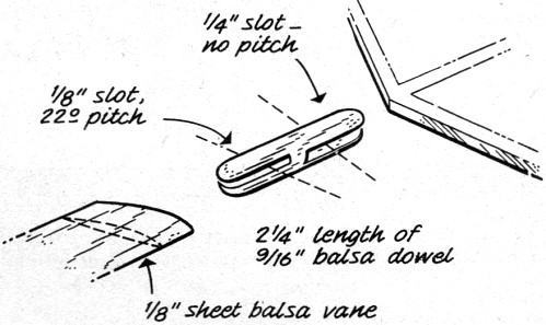
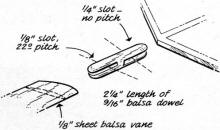
Make up the lifting vanes. Five are identical, except that one has a hole cut in it to allow for installation of
solder ballast. The sixth vane, to which the engine is mounted, is different in shape because it is bolted directly
to the framework. Note this vane operates flat - no pitch. The engine mount is a disk of plywood, pinned and cemented
to the vane and backed up with a soft balsa fairing. It may vary with the engine used. Mark out and drill the mounting
holes before installation. You'll need a good hot .049 size engine for best results. We used a Thimble Drome. Note
that the motor is mounted at an angle so that fuel will continue to feed under the effects of centrifugal force, The
propeller is mounted tangentially for most effective thrust.
|
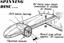
Power pod construction.
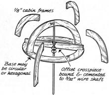
Cockpit construction.
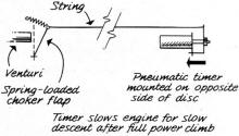
Timer configuration.
|
Assemble the vanes to the disc, then balance the motor weight by backing up the hole in the opposite vane with
some wood and puddling in solder over a few pins driven into the I.D. of the balancing hole. The balance weight should
equal the engine weight minus fuel ... a slightly out of balance condition will not affect flying very much. The cabin
axle is dropped through the holes in the disc axis; slide some fuel line tubing over the wire to retain it. Check
to make certain the disc revolves smoothly when held by the cabin axle.
|
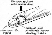
Counterweight details.
Paddle attachment. |
Flying: Take the model into an open area and start the motor. Lean it out until it is developing
full power, then lean it out just a bit more. Hold the model by the launching shaft and allow the disc to spin up
to full speed before releasing it. The model will go up whirling rapidly with a peculiar, characteristic droning noise
caused by the spinning engine. After rising for a distance the engine will begin to starve because of the lean setting
and the model will settle back to earth.
If you want to get longer flights from the model arrange a choke to a timer so that after a desired length of time
the motor is choked down to a four-cycle idle that brings it down.
This model was designed to be as simple as possible, consistent with good results. If it runs out of fuel at a
high altitude it will descend in a series of spectacular falling-leaf swoops ... so bring it down under power. Advanced
model makers may wish to experiment with automatic pitch control for the vanes which will bring the model down in
free-wheeling flight - but it will make the project a lot more complicated.
It's interesting to speculate upon the future of this type of real aircraft. Maybe you'll be seeing them howl by
overhead one of these days.
It's interesting to speculate upon the future of this type of real aircraft. Maybe you'll be seeing them howl by
overhead one of these days.
Spinning Disc Saucer Plans
Posted August 3, 2014
|