|
Website
visitor Bob B. wrote to ask for a scan of an article entitled "Airfoils
and Alternatives - The "Skinny Lifters," from the December 1974
American Aircraft Modeler. Author Eric Lister wrote about thin,
undercambered airfoils and their superior lift-to-drag (L/D) ratios.
I assume Mr. Lister is a California resident because he likes to
invoke bikinis and covering curves for an analogy. Whatever works
for you, I suppose! Airfoils and Alternatives - The "Skinny Lifters"
by Eric Lister
 This
month's column was born on a beach. You're expecting maybe a few
words on slope soaring? Sorry, the real origin of this month's effort
is due to bikini watching. Plain and simple, the message this time
is that the thickness of an airfoil is really like a bathing suit
- both are used to cover the structure. And neither adds to the
performance of the curved section. This
month's column was born on a beach. You're expecting maybe a few
words on slope soaring? Sorry, the real origin of this month's effort
is due to bikini watching. Plain and simple, the message this time
is that the thickness of an airfoil is really like a bathing suit
- both are used to cover the structure. And neither adds to the
performance of the curved section. To prove the point aerodynamically,
we'll produce a new airfoil that could be used as a substitute for
the NACA 6408 or 6409. It will have all the good lift characteristics
of these sections, but much less drag. To prove the point anatomically,
we'll have to wait until AAM comes up, with a centerfold (We're
working on it. All interested females drop the Editor a line).
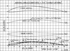
Click for 4x version of Skinny Lifters airfoil plots
The vehicle for explaining how we can do this will be the NACA four-digit
airfoil series. I picked this group because of its extreme flexibility
and the fact that almost everything you read here can be verified
from NACA information. Let's run through the NACA numbering
system. All airfoils in the NACA four-digit series have, naturally,
four digits as their title. The first number gives the amount of
max camber in percent chord. The second gives the location of the
max camber point in tenths of chord length. The last two digits
give the max thickness in percent chord. NACA 6408, for
example, would have 6% max camber located at 40% of the chord from
the leading edge, and would be 8% thick. Fig. 1 gives a sketch of
the airfoil. Fig. 2 shows the mean line of this section. Remember
that the meanline is the curved line that goes right through the
middle of the airfoil. Note that, as advertised, the NACA 6408 meanline
has a max height of 6% of chord length which is located at the 40%
chord location. So much for the four-digit numbering system.
Now comes the meat. During the past few months, this column has
been making new airfoils by modifying older proven ones. I've talked
about splitting airfoils up into rneanlines with thickness distributions,
altering the max camber and the max thickness, and adding them back
together again to get the new sections. The problem has
been that this is about as clear as mud unless you've had some experience
at it. Since the basic aim of AAM is to explain, not mystify, this
month we'll take the space to layout how it is actually done. This
will accomplish two things: first, you'll be able to make your own
airfoils, and second, you'll get some understanding of why the "Skinny
Lifters" ought to work out and how to make them. Let's start
with the NACA 6408. There are tables available in the four-digit
series that give coordinates for the meanlines, depending upon where
the max camber is located. In the master tables, all are given with
a 6% camber. For modelers, the ones of interest are those ranging
from 30% to 50% chord for the max camber location. This means the
63, 64, and 65 mean lines. The master tables, as I call them, are
included in this article. Here's where the flexibility comes
in. Suppose that what you want is an airfoil with a 44 meanline
instead of a 64. To get the 44 meanline all you do, if you don't
mind the effort, is to take all the height coordinates of the 64
and multiply them by the ratio of the desired camber divided by
six. For example, at the 20% chord location, the 64 mean line height
is a 4.50%. Multiplying 4.50 by 4/6 gives 3.00 as the height of
the 44 meanline at the 20% chord location. If you really want to
get into the design of things, the design lift coefficient, moment
coefficient, and design angle of attack (lowest drag) are also found
by multiplying the 64 values by the same ratio of 4/6. If you wanted
to make a 74 meanlined section, you'd multiply the 64 values by
7/6. The point is that the meanlines of the NACA four-digit
sections can be raised or lowered by simple multiplication. It takes
effort and patience, but it's no big technical problem. Worth noting
here is that once you know what your meanline is going to be or
is, this is what describes the lift characteristics of the airfoil.
If you look at the meanline of the 6408 section in Fig.
2, it's simply a line. If you could build an airfoil of sheet metal
and hold that shape, you could place it on any wing using an NACA
64 meanlined airfoil. You wouldn't have to change angle of attack,
or anything. The airplane would just fly flatter in the glide, or
faster if it were a powered ship. The catch in this, of course,
is that you can't build a zero thickness airfoil (on out-door ships
anyway). The bather usually needs a bathing suit, right?
Our aerodynamic bathing suit is the symmetrical airfoil. It's
used to keep spanwise spars and struts covered, because they would
really be drag makers in the open breeze. To avoid interfering with
the airfoil lift characteristics, the way the symmetrical section
is put on is to numerically add the upper half to the mean line,
then subtract the lower half from the meanline. For lift purposes,
you've done nothing to the airfoil. But, you have increased the
drag, as compared to that curved sheet metal meanline that would
do the same job. To illustrate quickly how this is actually
done, let's take the NACA 6408 at the 20% chord location again.
The meanline height was 4.5%. F rom the tables in this article,
the 0008 airfoil has a height of 3.83 or 8.33%. The 6408 lower surface
becomes 4.50 minus 3.83 or .67%. (Author's note: For modeling -
such as under one foot in chord length - this method of constructing
an airfoil is accurate to within 1/32". For super accurate work,
which is beyond most model building tolerances, the symmetrical
section's coordinates should be laid off perpendicular to the meanline.
At any rate, that's how I do it and most of my ships fly without
any drastic alteration required for trim. For
what it's worth, one more point of NACA four-digit flexibility should
be noted. The geometrics of symmetrical sections are all directly
proportional to each other. By getting the coordinates on one, you
can calculate exactly the coordinates for any other thickness. The
height values of the 0006, for example, can be obtained simply by
multiplying all the values from the 0008 by the ratio 6/8. Now for the "Skinny Lifters" - or how to fly with hardly any bathing
suit at all. A "Skinny Lifter" is simply a meanline made from sheet
material in the middle with hard leading and trailing edges to avoid
the rat-nibbled look. A section made this way is unlike a Jedelsky,
in that the sheet is curved by tossing in ribs every three to four
inches. The "6400 Skinny Lifter" shown in Fig. 4 is an attempt at
an NACA 6400 airfoil. This section would be a good substitute for
any 6409 airfoil. Its profile drag should be about 40% less than
that of a 6409 and its installed performance might be good enough
to give you a sailplane with 20% or so longer endurance. If you wanted to try for a 6500 series section, for example, just
use the 65 meanline shown in the chart. The important thing is to
preserve the meanline shape by making the sheet of a thickness so
that it just brackets the desired mean line.
Posted January 2, 2011
|