 [Table
of Contents]People old and young enjoy waxing nostalgic about and learning some of the history of early
electronics. Popular Electronics was published from October 1954 through April 1985. All copyrights (if any) are
hereby acknowledged.
See
Popular Electronics articles
on aircraft modeling. See all articles from
Popular Electronics. [Table
of Contents]People old and young enjoy waxing nostalgic about and learning some of the history of early
electronics. Popular Electronics was published from October 1954 through April 1985. All copyrights (if any) are
hereby acknowledged.
See
Popular Electronics articles
on aircraft modeling. See all articles from
Popular Electronics. |
Bill Winter is one of the best-known names in the aeromodeling realm
since he has been around writing columns on modeling events, construction,
flying, and product features, serving as editors of modeling magazines,
and participating in modeling events throughout the country since
the middle of the last century. He went above and beyond the call
of duty in his attempt to introduce people to the model aircraft
and model rocketry hobbies. This particular article is one of a
handful Bill wrote for Popular Electronics magazine in
the 1950s and 1960s. An amazing transformation has occurred in the
radio-control aspect in that when this article was published, participation
required knowledge of electronics, a larger hobby budget than your
average modeler, and a willingness to be continually battling problems.
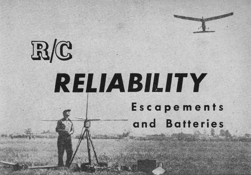
R/C Reliability Escapements and Batteries
By William Winter Editor, "Model Airplane News"
 Concluding
last month's discussion of reliability, that taken-for-granted device,
the escapement, had our attention. In the author's log, covering
15 radio control airplanes and thousands of flights, the escapement
was found to be second only to the relay as a cause of erratic control.
The point was made that the escapement should be considered as a
relay, since it has pull-in and drop-out currents which, aside from
the mechanical features, require observation, occasional adjustment,
and an accessible and removable installation that enables convenient
maintenance. Do not bury the escapement in a "blind" installation. Concluding
last month's discussion of reliability, that taken-for-granted device,
the escapement, had our attention. In the author's log, covering
15 radio control airplanes and thousands of flights, the escapement
was found to be second only to the relay as a cause of erratic control.
The point was made that the escapement should be considered as a
relay, since it has pull-in and drop-out currents which, aside from
the mechanical features, require observation, occasional adjustment,
and an accessible and removable installation that enables convenient
maintenance. Do not bury the escapement in a "blind" installation.
How the escapement works has been described in earlier articles
of this series, as well as in Mr. Safford's articles in this magazine.
Our concern now is how to keep one working. Properly installed and
regularly checked, the escapement is reliable. Any new escapement
should be examined and bench-tested before installation in the plane.
Howard Bonner, whose SN and compound escapement types are familiar
to all R/C modelers, states that the overlap of the revolving arm
or claw, on the pawl, should be 0.015 to 0.020, armature pulled
in. With the armature released, the claw should barely clear the
pawl. Also, when armature is pulled in, the claw should barely clear
the neutral pawl position. These values apply approximately to the
other familiar makes of escapements.
|
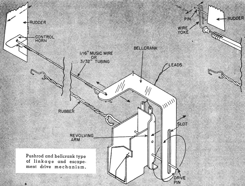
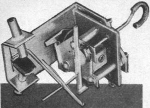
Pushrod and bellcrank type of linkage
and escapement drive mechanism.
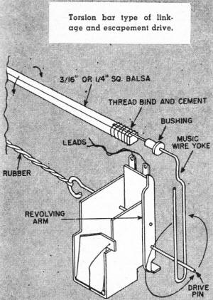
Torsion bar type of linkage and escapement
drive.
|
If the escapement functions suitably when hooked up on the bench,
leave it alone; the above figures are given as a rough guide in
the event that the item skips or sticks, requiring adjustment that
is unlikely when new. After operating the escapement perhaps 100
times on the work bench, examine it closely for burrs that might
develop where claw and pawl meet. The tiniest burr can prevent the
escapement's working in the air. Usually the escapement so afflicted
functions while the engine is running, but when the motor stops
and vibration disappears, response to a transmitted signal does
not occur. Sometimes new escapements develop burrs quickly, but
once smoothed off will function properly for long periods of time.
Set up batteries similar to those in the plane, also the same
size rubber strand wound to 20 per-cent excess of a single row of
knots (not counting the first row of turns). It is vital to check
the spring tension. Does the escapement always release when the
rubber is fully wound? Does the escapement always pull in and work
easily under simulated service conditions? One excellent way of
checking is to hook up a set of batteries with a potentiometer in
order to vary the voltage available to the escapement magnet, Increase
voltage gradually until the escapement armature pulls in. Just as
important, note the voltage at which the escapement releases. This
was the most important lesson learned by the writer in the 1954
flying season.
The escapement should never require more than 2 1/2 volts to
pull in and should not require a cutting off of current in order
to release. First, the pull in. Under load, two new 1 1/2 volt pen
cells in series drop off to 2 3/4, volts. As the no-load voltage
decreases with use, the voltage then available under load may be
less than the voltage required to pull in the escapement. Once during
a demonstration, the writer installed a new, unchecked escapement
and immediately lost control of the plane during the glide. A check
revealed that the escapement required 2 7/8 volts to pull! It is
best, therefore, to allow an adequate margin for falling voltage,
especially under load, by adjusting the escapement (its spring tension
is increased or decreased) to pull in at 2 to 2 1/4 volts.
Why is drop out so important? If spring tension is too low, the
flow of current '\has to be cut off to allow release of the escapement
armature. This is a timely tip that in the air the escapement may
not release. Many a crash has been attributed to interference, sticking
relays, etc., when the escapement was out of adjustment. The difficulty
is that if the condition is marginal, the escapement may appear
to function properly after the accident, so that cause of the accident
may be undetermined. Eventually, the spin-in will be repeated. Sometimes,
the plane has a mysterious tendency to come out of a turn very slowly
after the rudder is released or to continue overbanking momentarily
after the rudder goes back to neutral. This can be caused by a sticking
relay, but also suspect that escapement.
It has been found that if the escapement will release with current
caused by 1/4 volt flowing through the coil, it should release reliably
by spring tension in the air. The current is a measure of spring
tension.
Mounting affects an escapement. Do not screw an escapement base
tightly to a slightly warped piece of plywood. The frame bends,
throwing adjustments out. Then the modeler may file the end of the
revolving arm to make it shorter. Loosen the escapement and the
frame springs back into alignment. Now the gaps are too big and
the escapement is needlessly junked. So the mount must be firm (if
the escapement does not incorporate its own mount), never less than
1/8 inch thick plywood with the long edges reinforced with balsa
strips, and it should also be warp free.
It is important to use the proper rubber strand for the escapement
drive power and the correct voltages. The type of linkage affects
the required size of rubber. There are two types of familiar linkages.
First, the push rod connected between the rudder horn and the bell
crank, converts the rotary motion of the escapement drive pin into
linear motion. The second is the torsion bar, which is rocked back
and forth by the rotation of the escapement drive pin. The push
rod arrangement increases the load on the escapement, especially
during maneuvers (centrifugal force multiplies the weight of the
rod) when the entire weight of the linkage may have to be lifted
by the actuator. The torsion bar is easier to move, does not overload
the escapement and, therefore, favorably affects the size of rubber
which is required, in addition to escapement adjustment and operating
currents.
|
In this self-neutralizing escapement the mechanism is
also used to cover and uncover air bleeds in the fuel line
to control the motor.
|
With self-neutralizing escapements, 1/8 inch rubber has been used
with both push rod and torsion bar, although, in the author's opinion,
it is decidedly marginal in the case of the push rod, particularly
on a cold day when rubber loses much of its natural vitality. Therefore,
it is better to use 3/16 inch rubber with push rod deals. When using
3/16 inch rubber, allow 20 per-cent extra length over and above
the distance between hooks. This prevents too much tension being
placed on the escapement thrust bearing which could cause a jamming
action. The compound escapement should never be used with 1/8 inch
rubber with a push-rod linkage. The reason is that the compound
incorporates a rattle wheel to slow down the action of the escapement
and allow the man on the ground enough time to get off the required
number of pulses necessary for its operation. So the compound requires
more drive power than the self-neutralizing escapements.
Some builders claim that the flier must have a sense of timing
to pulse the compound (one, two, or three signals, depending on
the desired control). Therefore, they claim it is better to use
the weaker, 1/8 inch rubber to slow down the escapement so that
the flier can keep up with it. That is poor advice. The compound
can hang up when powered by 1/8 inch rubber, if only due to the
drag of the electrical contacts in the third control position. Actually,
it is better and easier to operate the compound with 3/16 rubber,
when the unit works faster instead of more slowly. With the 1/8
inch rubber, timing is important, because it is possible to pulse
too fast and pick up the wrong control. With the 3/16 inch rubber
it becomes impossible to pulse too fast with a Microswitch held
in the hand. At the same time it is not hard to pulse fast enough,
especially after a few practice dry runs on the bench. Even a mechanical
ground control unit will not time properly the 1/8 rubber driven
compound. As to reliability, the compound is often criticized, but
one of the author's compounds has given trouble-free operation equivalent
to three self neutralizing units.
It is frequently argued that the compound does not have the ability
to hold the rudder over when air speed picks up or to hold the plane
in a prolonged spiral, especially in the direction of the control
(usually left rudder) that requires two pulses. Supposedly, the
compound is not effective on big, heavy, fast machines. The truth
is that the compound is suited for all installations, provided an
aerodynamic surface (see drawing) is used along with the3/16 inch
rubber drive.
Blaming escapement ills on batteries is both commonplace and groundless.
People are forever putting 4 1/2 and even 6 volts on a 3-volt escapement.
Not only is this unnecessary under any circumstances, but it leads
to further complications. To begin with, battery drain is increased
greatly with higher voltages when the resistance of the coil remains
the same. This is a basic law of electricity. Therefore, the batteries
run down faster, not more slowly, when voltage is stepped up. A
5 ohm escapement which might function for several flying sessions
on 3 volts, may make only one long flight on 6 volts! Battery life
is increased by hooking batteries in parallel, not series. Most
planes can carry four pen cells, instead of the standard two, for
escapements. Two pen cells may give a dozen good flights, depending
on how many times the control is applied and how long it is held
on. Planes with slow response are rough on batteries all down the
line, even in the transmitter. Excessive voltage on many escapements
builds up a residual magnetism which can cause the armature to stick
in the control position. Higher actuator voltages accelerate damage
and dirt on the relay contacts.
With some builders, batteries may be the second or even first
source of trouble. In the writer's log they happen to be third,
mostly due to odd and unexpected failures, such as one abrupt failure
resulting from the battery having been dropped by a clerk. A connection
between cells gave way. This suggests care in the handling of "B"
type batteries.
Choose battery sizes that provide adequate life and reserve,
unless, of course, the plane is a midget. For example, two pen cells
on filament will give an afternoon's flying on a single (gas) tube
receiver. Such receivers have even been flown on one pen cell, but
if the plane will carry one or two medium flashlight cells, it is
an unwise risk. A two (gas) tuber will operate on two pen cells
for a busy half-day flying session, but two mediums would last for
weeks. Similarly, why fly on 22 1/2 or 30 volt hearing aid "B" batteries
(in series for 45, 67, 60 volts, etc.)? A single Burgess XX-30 or
K-45 or the equivalent in other brands will last for weeks, if not
months. The typical transmitter will operate for at least a season
on Burgess M-30's or larger (or the equivalents). Hearing aid "B"
batteries certainly are not desirable for long term results with
hard tube receivers that idle at 3 or 4 mils. Two mediums on an
escapement may last a summer.
Possibly the gravest error made by the beginner is to measure
voltages without placing a load on the batteries. The transmitter
should be checked with filament turned on, Microswitch closed for
"B's." It will be noted that "B" batteries may drop several volts
under load, but this is normal. On the other hand, a drop of 10
volts or more from the initial reading (not new voltage necessarily)
under observation means that the batteries are weak. Hold the meter
probes in place for 5 to 10 seconds and watch for a slight, steady
falling off in voltage. The battery is no good. Do not operate anywhere
near the minimums specified by the radio manufacturer. The writer
discards flight "A" batteries that read 1.4 volts or less under
load, when 1.5 volts is the normal filament voltage. The voltage
can drop further in the air and 1.3 volts is the safe minimum.
For 3 volt escapements, a bitter-end 2 1/2 volt minimum under
load is desirable, unless the escapement happens to be one that
works on 1.5 volts, as does the Macnabb Citizenship. After a 67
volt "B" battery drops 5 volts to about 62 volts, there is no percentage
in continuing it in service. Battery costs are low compared with
the total cost of plane, radio, engine.
In cold weather, allowance must be made for a falling off of
voltage due to temperature. Some modelers keep batteries in a warm
place, as in the pocket or on a car heater. Obviously, this is inconvenient,
but batteries should be allowed to recuperate between long flights.
It is a good rule to allow the batteries to rest for a period twice
as long as the last flight. Between flying sessions, batteries recuperate
so that they almost regain the normal new voltage. After that, they
should be checked after every few flights.
Make it a rule to check batteries before going out to the flying
field. If they are down to a serious degree, install new ones and
enjoy an outing free of concern.
Posted March 14, 2015
|