|
September 1956 Popular Electronics
 Table of Contents Table of Contents
People old and young enjoy waxing nostalgic about and learning some of the
history of early electronics. Popular Electronics was published from October 1954 through April 1985. All copyrights (if any) are
hereby acknowledged.
See
Popular Electronics articles
on aircraft modeling. See all articles from
Popular Electronics.
|
If you are relatively new to radio control
(R/C) operation, whether for the latest 'drone' craze
(technically multi-rotor aircraft), model cars, model boats, helicopters,
or airplanes - or even robots, then you might be interested in discovering a little about the systems
which pioneers in the sport had to work with. In the mid 1950s when this article appeared in Popular
Electronics magazine, multi-rotors and helicopters were not even in the list of model types. As
with radios and television sets, before the convenience and performance increase brought about by the
advent of solid state components, R/C modelers struggled with vacuum tube equipment, too. If you are
old enough to remember needing to re-tune your radio or TV occasionally due to frequency drift, then
you can believe the same thing occurred with vacuum tube R/C systems. This could and often did prove
to be quite unfortunate in airborne systems where vibration from an internal combustion engine worsened
frequency instability and many times resulted in loss of control with a subsequent crash. We are collectively
once again thankful for those who forged a path through the figurative electronics wilderness to get
us safely to where we are today.
Simple Dual Proportional R/C System
By R. L McIntyre
|

You can fly high, wide and handsome if you add elevator control to your R/C model
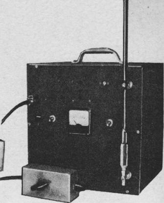
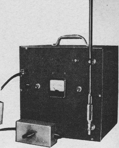
Front view of the transmitter with its 24" antenna and the dual control box; this
transmitter can be used with simple push-button control for escapement by plugging another cord in unused
plug on front panel.
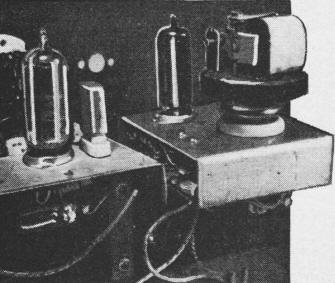
Close-up of the pulser and transmitter; pilot lamp shown just under transmitter is
in series with the crystal to protect it from excess current.
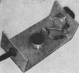
An internal view of the pulser control box - the control at the end is the elevator
control and the one at the top is the rudder control.
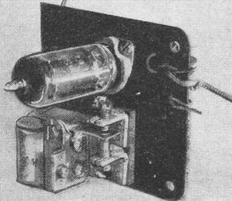
Top view of the elevator unit showing the relay and tube. Note that although a 3S4
tube appears in this photo, the correct tube to use is a 3V4 as shown on the circuit diagram.
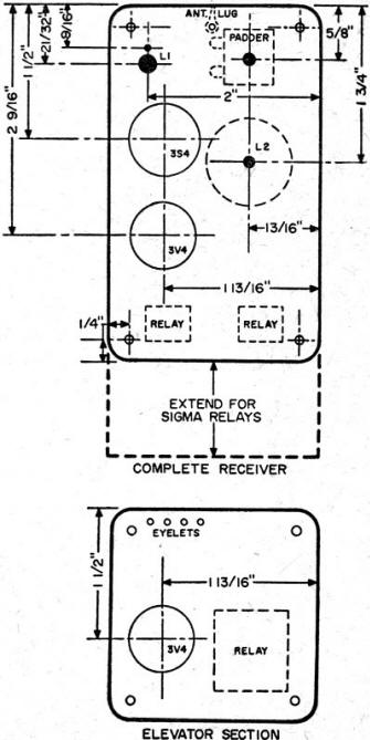
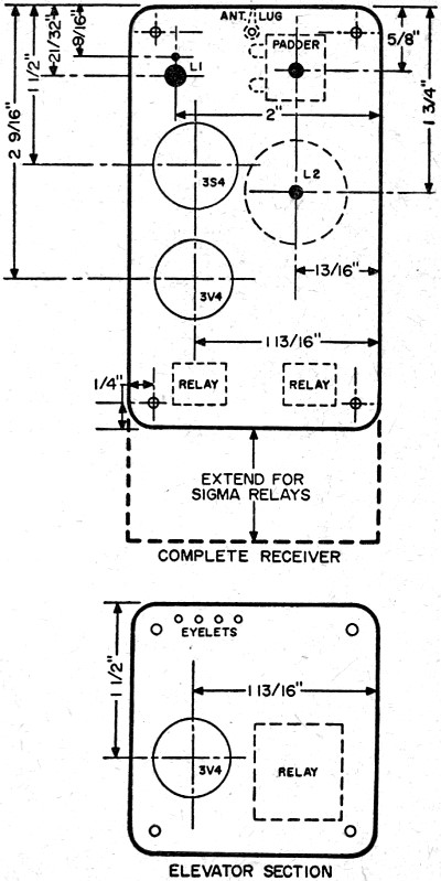
Dimensional drawings of the complete receiver (at top) and the elevator section (at
bottom).
|
If you have wanted to enjoy the added thrill of elevator control along with rudder control on that
favorite R/C model, but can't afford the cost or weight of a tone control system, this article is for
you. The system described here offers two proportional controls on one channel, and it uses a standard
transmitter and receiver as building blocks.
When flying with this dual proportional system, the flyer has two controls: the rudder control which
varies the pulse width, and the elevator control which varies the pulse repetition rate. Continuous
control is always available by merely regulating the resistance of potentiometers R8 and R10. Thus,
it is easy to develop the feel of flying with this system.
The heart of the system is the pulser. This is the unit which does the actual controlling of the
model; so it is necessary to observe a few precautions during its construction.
Pulser Construction. Layout of the pulser is not critical, but I prefer to keep
the control box as a separate unit as it allows greater freedom of movement. You can build the pulser
as a complete unit if you wish. If you follow my design, be sure that the control box is small enough
to be held in your hand comfortably, and yet large enough to contain the two potentiometers. The cable
used to connect the control box to the pulser should be of the shielded two-conductor type. Ground the
shield to the arm of R8 (rudder) and to the pulser chassis to avoid hand capacity changes.
Any plate-type relay may be substituted for the Sigma 4F (RL3) as long as you change the value of
R5 so that its resistance -plus that of the relay you substitute - adds up to 12,000 ohms. A common
connection between A-plus and B-minus is necessary to stabilize the neutral rudder at all elevator positions.
As the 3A5 tube (V3) has a high-filament drain, the A battery should be fairly large.
One word of warning! If you are now flying proportional rudder and the pulse stops at full rudder
positions, the elevator will be in the full-up position. If your pulser does stop in this manner, increase
values of resistors R6 and R7 in the grid circuits. If you wish to reset the pulse rates - the lowest
rate is set by increasing the values of C5 and C6, and the highest rate is set by reducing the value
of resistor R9 in series with Rl0.
For those who have proportional rudder control installed and want to add the elevator section to
a receiver, I have included a diagram of the base I used as shown in the photographs of the elevator
control. The receiver should have a plate current drop of approximately 1 ma. on receipt of signal.
If it meets this requirement, then mount the 3V4 tube, relay and other components on the base as shown,
keeping the lead from the original receiver to C4 as short as possible. Refer to the completereceiver
construction for details on building and tuning the elevator control.
Receiver Construction. First layout the base and drill all holes in a piece of 1/16
linen base Bakelite. The tube sockets are mounted about 1/2" below the base on eyelets or spacers. With
the sockets in place, mount L1, C1 and L2 permanently in place, in the positions shown. Check to see
if the relays fit, but do not keep them on the base as they may be damaged by solder.
Work one lead of RFC1 between the socket for V1 and L2 so that it reaches its terminal on L2. Shape
the other lead to reach the front terminal of the padder C1, but do not solder. Connect a piece of solid
tinned wire from, the back terminal of C1 to L2 and solder at 0C1 only.
Connect C2 from L2 to pin 3 of V1. Solder at L2, then connect R1 from pin 3 to pin 5 and solder at
pin 3.
Take another piece of wire and connect it from pin 2 to pin 4 of V1 and then to the outside terminal
of L1. You can now solder all three points. Connect the other terminal of L1 (see schematic) to the
front terminal of C1 and up to L2. Solder these points:
Attach C3 from L2 to pin 5, with the marked end of C3 closest to the pin. RFC3 is connected from
pin5 of V1 to pin 5 of V2. Solder at V2. Connect RFC2 from pin 1 of V1 to pin 1 of V2, and C4 from pin
6 of V2 to L2 - leaving the lead on C4 long enough to reach the relay. Solder at L2.
Connect R2 and CR1 from pin 6 to pin 4 of V2. Solder pin 6, then solder in R3 from pin 4 to 5 of
V2. Using solid wire, solder leads from pin 2 and pin 3 of V2 long enough to reach relay. Connect A
and B battery leads to pin 5 of V1, then solder.
You can now mount both relays. Connect the leads from L2, and pins 2 and 3 of V2 to the elevator
relay and solder. Connect the B-plus lead to the unused end of each relay, the A-plus lead to pin 1
of V1, and solder all connections.
Carefully check the finished unit against the schematic, then connect the batteries and check the
voltages on the tube sockets. You should have 45 volts from pin 5 to pin 2 and 1.5 volts from pin 5
to pin 1 on both tube sockets.
Tuning. The procedure for tuning the receiver should be followed closely. Insert
the 3S4 only, and connect the filament batteries. Then connect a 25,000-ohm potentiometer in series
with the 45-volt B-plus lead through a milliammeter to the set as shown in the schematic.
Adjust the external series potentiometer to allow 1.7 ma. of current to flow, then set the rudder
relay to pull in. Readjust to give 1.5 ma. and set the relay to drop out.
To adjust the elevator relay, insert the 3V4 and set the series potentiometer. The current is now
the total of rudder current and elevator current, so subtract the rudder current to get the correct
reading.
Remove the 3V4 and tune the receiver to 27,255 mc. by watching for a dip in receiver plate current
as you key the transmitter. This dip should be 1 ma. It can be adjusted by turning the padder capacitor
to the left until the current drops off and then giving it one-half turn to the right.
Replace the 3V4 and key the transmitter. The rudder relay should drop out and stay out as long as
the key is closed. The elevator relay should drop out momentarily and close again almost immediately.
Should the elevator relay stay open, check the wiring.
If the wiring is correct, reduce C4 from 0.04 μfd. to 0.03 μfd. and try again. This capacitor
should be as large as possible and not cause the elevator to follow the rudder.
The unit is now ready to install with any activator. I used the one put out by Southwestern Electronics,
Houston, Texas, although another unit could have been employed.
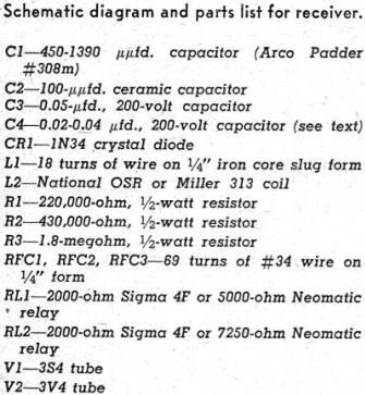
All of the parts may be obtained at most radio supply houses. The Miller # 313 coil can be used in
place of the National OSR with about 1 ma. more plate current being the only difference in operation.
Any slug-tuned coil that will tune to 27,255 mc. may be used for L1, and the 1N34 can be replaced by
nearly any germanium diode.
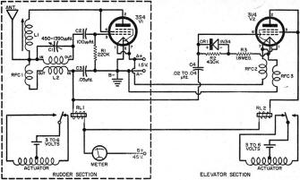
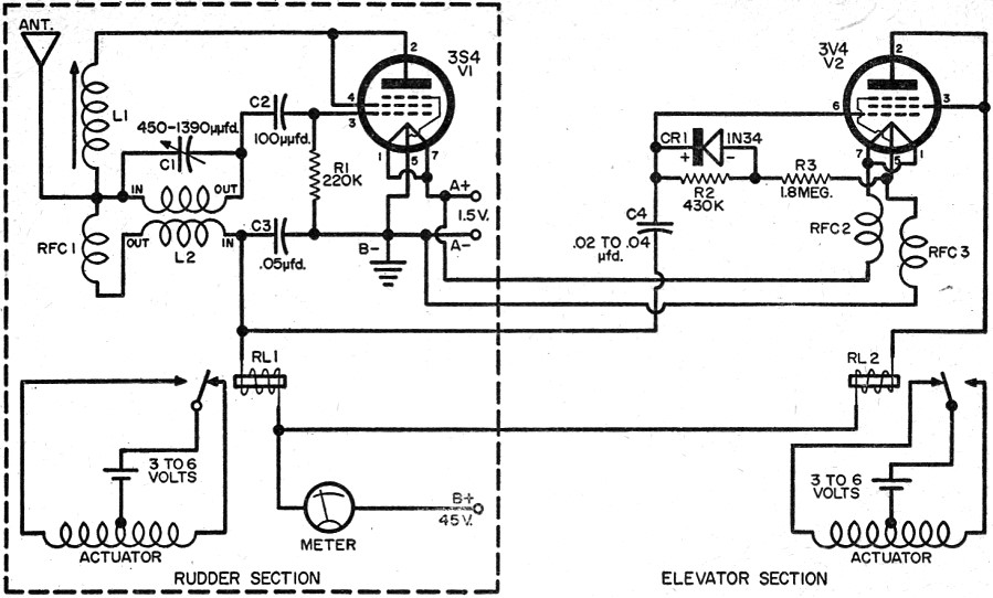
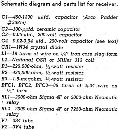
Schematic diagram (above) and parts list for receiver
(below).
Posted March 29, 2015
|