|
This Nufnut free
flight model airplane article and
plans came to being in response to laments from would-be model airplane builders
who tried and failed at their first (and sometimes more) attempts to make and fly
something even as simple as a rubber powered model. The author decided to present
detailed instructions on building and covering an open frame stick and tissue model,
being sure to detail areas that generally cause the most trouble. The most difficult
task for most beginners is covering the airframe with tissue and then obtaining
a warp-free structure after application of dope. If you are new to the hobby and
either have experienced such disappointments or are considering getting into the
fine hobby of model airplane building and flying and seek sage advice on how to
avoid discouraging pitfalls, then you have come to the right place. Tufnut
is a somewhat unique design with its solid balsa fuselage that has a slot cut in
it for containing the rubber band, rather than just using a stick with the rubber
hanging underneath.
Tufnut Article & Plans
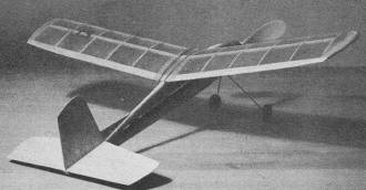
Simple, robust construction should enable youngest reader to
duplicate this natty looking craft. Although balsa profile fuselage helps beginners,
the built-up wing takes ship out of all-wood class.
Full size plans in magazine, detailed step-by-step construction
notes, make this delightful little rubber job a quickie project for that sport flying.
by P. G. F. Chinn
"To: The Editor,
Model Airplane News.
"Dear Sir,
Recently I took up building model planes. I bought a rubber driven model but
when I tried to assemble it, I ran into trouble. My wing was crooked and when I
tried to paper it, the paper wrinkled and I couldn't seem to get the rounded body
at all ... "
This is part of a letter received recently by MAN. It is typical of a number
of such letters regularly reaching this magazine. So the editor conducted a little
research: he found that model building loses vast numbers of promising new members
through beginners' failing to complete their first model successfully and he found
out some of the reasons for such failures.
Firstly, of course, there is the age-old problem of the beginner trying to build
something that looks good on paper but is much too tricky or tedious for him to
tackle at such an early stage.
Secondly, there is a tendency for designers and manufacturers to over-emphasize
performance. For high performance, a high power-to-weight ratio is needed and that
means a light and relatively flimsy model. A flimsy model not only breaks when it
hits something; it is difficult to keep in shape when you cover it, through the
lack of rigidity in the framework. Moreover, such a model doesn't even have to crash
to get broken: it can all too easily be accidentally damaged in handling. All this
means that our "high performance" model will probably never get into the air, or,
if it does, it will never get a chance to perform as the designer intended. Besides,
long flights really aren't necessary. You will be surprised to see how long even
a 20 or 30 second flight really is and how thrilling it can be.
So, bearing all these points in mind, we set about trying to provide a model
design and construction feature that would give the beginner a better chance of
success. "Tufnut" is the result.
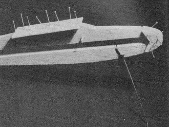
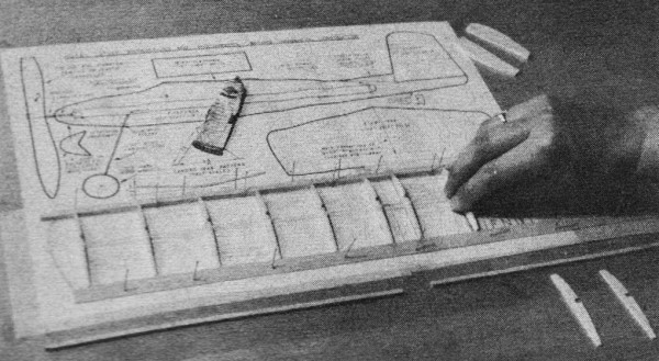
After cutting out fuselage, add wing platform, nose reinforcement,
landing gear, as shown here.
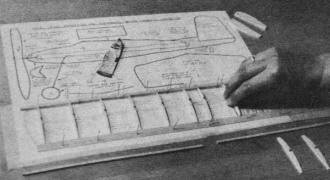
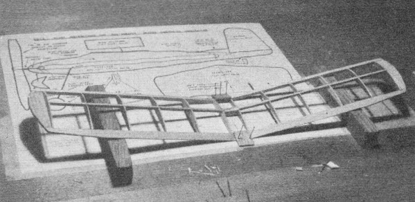
Cover plan with transparent wax paper and assemble wing by pinning
down parts shown and cementing ribs in place. Wing spar goes on top.

When wing is built, notch leading and trailing edges at the dihedral
break and block up each panel to form correct dihedral angle. Cement.
At first, we had intended to make it a traditional "stick" model. We chose, instead,
the profile-fuselage type for three reasons: it is stronger, it rules out the need
for making a special metal propeller bracket and it looks more attractive.
To answer our second requirement, we nave made the plans as easy to understand
as possible and supplemented them with a series of photographs, taken during the
construction of the original model, to show the various stages in its assembly.
These pictures are referred to in the detailed instructions which we shall come
to in a moment.
In answer to our third point, Tufnut really is tough. We gave the original model
to two young friends of ours who immediately flew it into the side of a shed and
then crashed it several times in quick succession because of their inexperience,
but it came through with no damage.
The solid 1/4 in. sheet balsa fuselage is stronger than one of built-up strip
balsa and tissue. The tail unit is simply cut from 1/32 in. sheet, which is quite
strong enough, and this, and the various fittings, such as landing gear and prop
assembly, are fixed with a minimum of trouble. For utmost ease of construction,
the wing, like the rail, could have been made of sheet balsa, but such over-simplification
does little to prepare the beginner for bigger and better projects and so we have
provided an efficient double-surfaced, built-up wing which is of sufficiently heavy
construction to simplify covering and resist damage in a crash.
The ready-made wheels may be of hardwood plastic, either of which can be obtained
from your local model dealer. You can use a ready-made prop, too. We used a 7 in.
Kaysun plastic prop supplied by America's Hobby Center. For longer flights, you
can use an 8 in. saw-cut balsa prop, if you don't mind a little extra work finishing
it off.
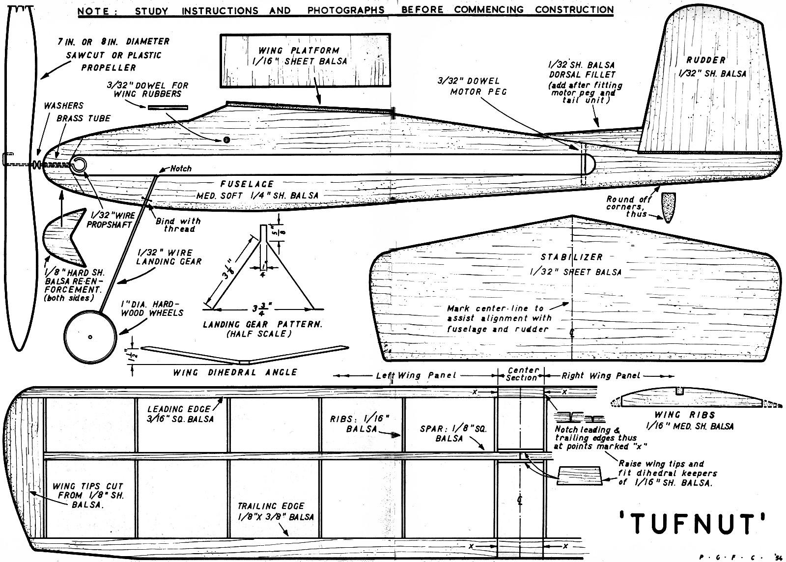
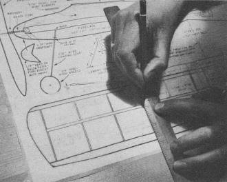
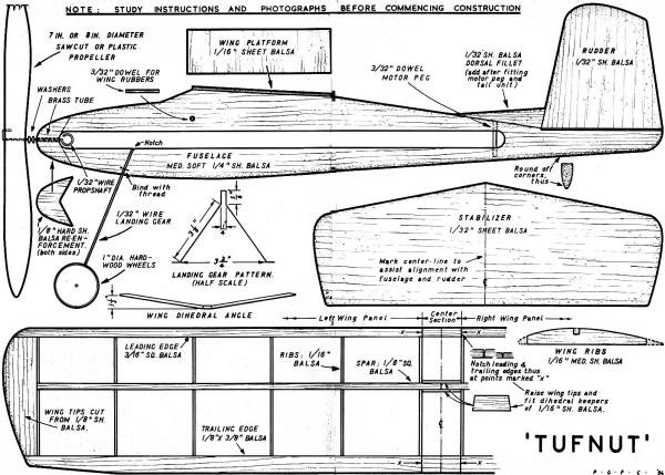
Before you attempt to start construction, take a good look at the full size plan
printed here and study all the photos. We would also recommend that you read through
the rest of this article so that you are quite sure that you understand everything
in advance. In this way you will eliminate the likelihood of making a mistake and
having to rebuild any parts.
The first thing to do is to cut out the various sheet balsa parts. To do this,
detach plan and trace outlines onto the wood with a piece of carbon paper laid under
the plan. Make sure that you have the grain of the wood running in the right direction
as indicated on the plan. Note, for example, that the grain of, the rudder runs
vertically, not across. Don't use warped balsawood, especially in the case of the
1/32 in. material for the tail surfaces.
For cutting out the parts, use a modeling knife or a steel backed razor blade.
Keep the blade upright, especially when cutting thick wood, such as the fuselage.
When making the wing ribs, you may use one of two methods. The first method is to
cut out all the ribs individually: an aid here is to make a thin metal or plywood
pattern to the shape of the rib, as given on the plan, and then to lay this on the
balsa and cut around it. The second method is to pin together 12 pieces of 1/16
in. sheet balsa, each measuring 2-11/16 in. x 3/8 in., to form a block 3/4 in. thick.
The top of this block is then rounded off with a sandpaper block to obtain the required
rib shape and, after cutting the slot for the spar, the finished ribs are separated.
When bending the landing gear, use a pair of pliers and start from the center,
where the legs join the fuselage. A shallow slot, or notch, is cut in the fuselage
at this point and the landing gear is then "sewn" to the fuselage with thread, two,
small holes being bored through for this purpose with a 1/32 in. drill or a piece
of wire. A drill will also be useful for boring the 3/32 in. dia. holes for the
dowel for the wing rubber and rear motor peg. Secure these with cement and also
put a little cement around the landing gear notch and binding.
The next thing to do is to add the two side pieces which reinforce the nose.
"Pre-cement" the joints by rubbing cement into the four surfaces to be joined. When
these are dry, apply more cement and pin the strengtheners to each side of the nose.
At this stage, too, the wing platform should be added. Having made sure that the
fuselage is quite flat and at the right angle at this point, pre-cement this, too,
and then pin in position .
The tail unit is the next thing to fit. Again, check that the fuselage is true
and flat, then pre-cement the surface. When dry, cement and pin the stabilizer in
position, after accurately aligning it. Let this dry for a while, then remove pins
and cement rudder in position, again after pre-cementing. When fitting the rudder,
view the model from the front to make sure that the rudder is in line. Finally,
add the small dorsal fillet which helps to strengthen the rudder fitting.
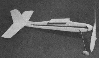
To finished fuselage add prop shaft and bearing, wheels. Cement,
temporarily pin stabilizer in place, then the vertical tail surface and fin.
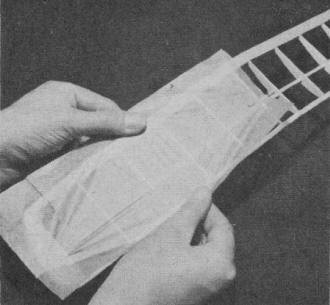
Pin plan to building board, then make tracing of wing-half. Use
drawing to complete wing plan as seen, bottom, outside photo opposite page.
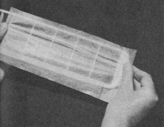
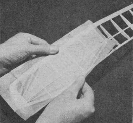
Commence covering on bottom surface by stretching tissue tip
to tip. Follow the directions.
After sticking ends at one point, pull tissue across wing, as
shown, and work toward the tips.
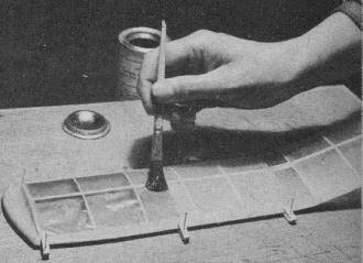
Dope underside first. Support edges on scraps 1/8 balsa, pin
down, then dope the top surface.
The wheels may now be added. These are just slipped over the axles, the latter
being bent up at the ends to retain them, or, if preferred, wheel retaining collars
can be fitted. A piece of brass tubing, 1/2 in. long, is used as a propeller shaft
bearing. The nose of the fuselage is carefully drilled or reamed our to the required
size and the tube then inserted with plenty of cement to secure it. At this stage,
the corners of the fuselage and the nose may be rounded off with sandpaper.
The prop shaft should have the rubber motor hook bent to shape first. It should
then be passed through the nose bearing and, after adding two washers, the propeller
may be fitted. If a plastic prop is being used, it will first be necessary very
carefully to drill a 1/32 in. dia. hole in the hub parallel to the shaft hole. The
end of the shaft is then bent over and pulled back into this hole as shown on the
plan. This completes the first stage of the assembly. We now come to the wing construction
and covering.
You will note that only the left-hand wing is shown in the plan. The first thing
to do, therefore, is make an accurate tracing of this. This tracing is then reversed
to give us the right-hand wing panel and is then added to the plan as shown. Make
sure that you have the two half drawings accurately aligned. If you do not want
to spoil your plan, it is a good idea to cover it with a piece of transparent waxed
paper. This will prevent the framework from sticking to it. If waxed paper is not
available, a piece of grease-proof paper, although not quite so satisfactory, will
do.
Start assembling the wing by pinning the full length leaning and trailing edge
strips in place. Ready-shaped, trailing edge stock is available at most dealers
and saves the necessity of sanding down to the required triangular section.
Now insert the ribs at the various stations as shown on the plan. Pre-cement
each joint for maximum strength and make sure that each rib is upright. Add the
1/8 in. sheet balsa wing tips and then fit the center spar. This spar is in two
pans, left and right, and there should be a 3/16 in. gap in the center to allow
it to close up when the tips are raised for the dihedral angle.
When the wing structure has been completed, the leading and trailing edges should
be notched, as shown on the plan, to allow the outer panels to be raised at the
tips. The center section should be very firmly pinned down to the building board
and each tip blocked up 1-1/2 in. after squeezing some cement into the notches.
Finally, the dihedral keepers should be cemented in place and the whole assembly
allowed to set for about one hour. After this, it may be removed from the board
and the leading edges and tips rounded off with sandpaper.
We now come to the job of covering the wing with tissue. You. may find this just
a bit tricky and tedious at first. We can only say that even the experts found covering
tricky when they first started to build model airplanes and that when you have built
one model plane, you will find that covering the next one is a lot easier.
Model tissue comes in various colors and grades. We would recommend an American
tissue, such as Silkspan, rather than one of the Japanese varieties. Japanese tissue
may be all very well for lightweight contest jobs, but Silkspan is a lot easier
to apply. Dope is usually employed for sticking the tissue to the frame. This means
that you have to work fairly fast because dopes dry quickly. We believe that Kodak
photo paste is more suited to the beginner. This dries more slowly and gives the
builder more time to get his tissue onto the framework evenly; also, the paste is
not so wet and does not soak into the tissue and temporarily weaken it during the
process of pulling the covering over the framework. As a substitute, mix a little
cement and dope, but use this only for sticking down edges of the paper.
When you buy a sheet of tissue, it may be a bit creased and wrinkled. It is worth
while, in this case, to smooth it out with a warm iron. The next thing to do is
to lay the wing on the tissue and cut a piece large enough to cover the bottom surface
of one side. Tissue has a "grain" and its maximum shrinkage is always at right-angles
to this grain. It is generally advisable to have the shrinkage spanwise so as to
prevent undue "sag" between the ribs. Therefore, make sure that your grain runs
across the wing: i.e., from leading to trailing edge. Also, be sure to cut the tissue
with about 1/2 in. surplus margin.
Have your work table cleared of everything except the items essential to the
job: tissue, good sharp razor blade, tissue adhesive and, of course, the wing. With
your first piece of tissue cut to size, apply paste to the framework. Paste the
tip first, then the trailing edge, then root (center) rib and leading edge. Do not
apply adhesive to any of the other ribs.
Now carefully lay the tissue over the panel and gently pull it out span wise.
Next, draw the tissue across the chord at the center of the panel. Finally, work
toward the four corners, carefully easing out the wrinkles and folds.
Do not press the tissue too firmly onto the framework until you have it pulled
out to your complete satisfaction. The advantage of Kodak paste is that it just
tacks the covering as you work, thus enabling any part to be unstuck, if a wrinkle
should appear, and stuck down again after the wrinkle has been pulled out.
Don't try to pull the covering drum tight. It will become tight with subsequent
shrinking and doping. Simply concentrate on getting the tissue applied evenly without
any bad wrinkles.
The surplus tissue may now be trimmed off and the raw edge stuck down. Cover
the other wing panel in the same way and then the two upper surfaces. When dealing
with the top surfaces, it is generally easier to cover the tip separately with a
small piece of tissue between the tip rib and the edge of the wing tip itself. Finally,
cut two strips approximately 1-1/4 in. wide and apply to the center section.
For shrinking and doping, it is essential to have a true, fiat surface on which
the wing can be pinned so as to prevent warping. If your building board is not entirely
free from warps, select a short piece of board that is. You will also need about
a dozen scraps of sheet balsa, about 1/2 in. by 1/4 in. and 3/32 in. or 1/8 in.
thick.
Some expert modelers, long practiced in the art of tissue covering, do not use
water-shrinkage, but, generally, it is advisable for the beginner to water shrink
before doping. For this, you will need a simple spray, either an old perfume spray
or a simple mouth type spray.
Spray the underside of one wing panel first. The tissue will be seen to go quite
slack. Using six of the small scraps of balsa under the wing to hold the wet tissue
from contact with the board, pin it down, using six more scraps on the top surface.
Now water-spray the top of the wing.
After a while the covering will dry out. It may not be completely tight, but
this does not matter. Repeat the procedure with the other wing panel.
The same system of pinning down is adopted when doping. Dope has two purposes:
to pull the covering tight over the framework and to make it airproof. Make sure.
that the covering is absolutely dry (following the water shrinking ) before applying
dope, otherwise you will find ugly white "blush" marks appearing on the covering
when dry.
Apply the dope with a soft doping brush and do not go back over any part previously
covered as dope soon becomes tacky. Again, the tissue will go slack, but when dry,
you will see that it has become tight and strong and that, as a result, your wing
is now quite rigid.
The longer you leave your wing panels pinned down, the better. So, though you
may be tempted to fit the wing as soon as it is dry and go out and fly the model,
it is much wiser to leave it undisturbed for a day or two, or, at least, overnight.
While waiting for the wing panels to dry, you can apply a couple of coats of
dope to the fuselage (and to the prop if a balsa one is used). This will make the
surface of the wood more durable. Do not, however, dope the rudder or stabilizer
as these are likely to warp if so treated.
The model is powered with four strands of 1/8 in. rubber. Make this up into a
loop
from a piece 38 in. long. Fit the wing to the wing platform with a long rubber
band (or two bands joined together) through the motor slot, over the wing and onto
the peg on each side of the fuselage.
Ready for flight, the model should balance on the finger tips when supported
beneath the wing center spar. If the model is slightly nose heavy, the wing can
be moved forward fractionally on its mount to compensate for this. If it should
be tail heavy, move the wing back. If the balance point (center of gravity) is badly
out, it will be necessary to add a small amount of clay to the nose or tail, but
this will not be necessary if you have built the model accurately.
Hand-launch the model gently into the wind to test its glide. Move the wing slightly
if it shows nose- or tail-heavy tendencies. Next, wind 50 turns on the motor and
try again, then 100 turns. On 100 turns, the model should climb up to 15 ft. or
so and fly a distance of 100 to 150 ft. You will now be able to see whether it flies
in the desired direction. Gently bend the rudder, after breathing on it, if the
model turns too sharply to one side.
On anything more than 100 turns, the model will rise off ground. You will probably
find that 300 turns will give you a very satisfactory flight, with a minimum of
time spent on rewinding. Actually, the motor, if properly treated with rubber lubricant,
will take many more turns than this, but the life of the rubber is greatly extended
by not winding to the maximum.
Take your time in building Tufnut. In return, you will have a model that will
give you hours of fun and provide you with the necessary experience for tackling
more advanced models.
One piece medium soft balsa 15 x 2 x 1/4 for fuselage; one piece medium balsa
12 x 3 x 1/32 for tail surfaces; one piece medium balsa 12 x 2 x 1/16 for ribs,
wing-platform, etc.; one piece medium balsa 4 x 2 x 1/8 for tips, etc.; one strip
trailing-edge stock 20 x 3/8 x 1/8; one strip medium balsa 20 x 3/16 x 3/16 for
leading edge; one strip medium balsa 20 x 1/8 x 1/8 for center spar; 12 in. 1/32
steel wire for landing gear and propshaft; 1/2 in. brass tube and two washers to
fit above; 2 in. 3/32 hardwood dowel; one pair 1 in. hardwood or plastic wheels;
one 8 in. or 7 in. dia. plastic or balsa prop; 38 in. 1/8 in. flat rubber; one sheet
model tissue; one tube model cement; one small bottle clear dope; one small bottle
rubber lubricant.
Tufnut Plans
Notice:
The AMA Plans Service offers a
full-size version of many of the plans show here at a very reasonable cost. They
will scale the plans any size for you. It is always best to buy printed plans because
my scanner versions often have distortions that can cause parts to fit poorly. Purchasing
plans also help to support the operation of the
Academy of Model Aeronautics - the #1
advocate for model aviation throughout the world. If the AMA no longer has this
plan on file, I will be glad to send you my higher resolution version.
Try my Scale Calculator for
Model Airplane Plans.
Posted June 13, 2020
|