|
This installment of Howard McEntee's Getting Started in R/C
column introduces electronic schematic symbols commonly found in
transistorized radio control equipment. In 1968, when this article
was printed, nearly all solid state circuitry was built from individual
discretely packaged transistors and diodes; integrated circuits
(ICs) were still a few years off for R/C equipment. If you look
at a modern transmitter or receiver schematic, you might not see
a single transistor symbol, and possibly the only diode to be found
will be one in series with the battery to prevent reverse polarity
connections. It is not that the transistors and diodes are not there,
it is that they have been absorbed into the IC packages.
Getting Started in R/C: Electronics Symbols
How Circuit Symbols Grow into Circuits: Eleventh in a Series
Howard Mc Entee
 When
we had completed Part 9 of this series, we had no intention of going
any further with description of circuit symbols, what they mean,
how they are used. But it seemed a shame to completely drop the
subject when it came time to write Part 10, so that part went a
bit more into the subject, even showing a simple diagram of a Simpro
control system - and again we had intended to go on to other subjects.
Well, more of the same follows below - but this will be the last
of the matter. When
we had completed Part 9 of this series, we had no intention of going
any further with description of circuit symbols, what they mean,
how they are used. But it seemed a shame to completely drop the
subject when it came time to write Part 10, so that part went a
bit more into the subject, even showing a simple diagram of a Simpro
control system - and again we had intended to go on to other subjects.
Well, more of the same follows below - but this will be the last
of the matter.
This time we cover a few remaining common circuit symbols you
will see quite frequently in this and other model magazines, then
go on to a couple of circuits, to show how all the parts we have
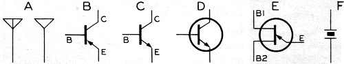
described tie together. At A herewith you see two symbols that indicate
the antenna, either transmitter or receiver. There is no difference
between the two we depict, but that at left is probably more common,
and is the one we use in A.A.M. The symbol does not indicate how
long the antenna should be; if length is important, it is simply
given via a figure for inches or feet.
Transistors are in many circuits nowadays - we might even say,
in most. The more common types are shown here. At B is the so-called
PNP transistor, while the NPN is seen at C. We won't go into the
internal differences, which have to do with the actual material
of which the transistor is made, and the battery polarity. Suffice
to say that many circuits require both types, and the only symbol
difference is in the direction of the arrow on the emitter (or E)
lead.
This is extremely important. The B on the left-hand lead stands
for Base, the C on the upper right one for Collector. Often you'll
see the "bare" transistor symbol with a circle around it, as in
D. This circle has no meaning at all - it just dresses up the circuit
and serves to set the transistor apart from all other circuit elements
and the actual wiring. Note that the B, C and E are often omitted
from the transistor symbols in circuits, but one who is hep to the
symbols utilized will know which is which - and also if the transistor
is PNP or NPN - at a glance.
 At
E we have a slightly different style of transistor, which is. actually
different internally from those in Band C, and which is often seen
in pulser or tone modulator circuits. It is called the "unijunction"
transistor. This one does not have a collector (C symbol), but there
is an emitter, and two base leads, E, B1 and B2 respectively. Such
transistors are especially useful as low frequency oscillators,
hence their popularity in pulse and tone circuits. At
E we have a slightly different style of transistor, which is. actually
different internally from those in Band C, and which is often seen
in pulser or tone modulator circuits. It is called the "unijunction"
transistor. This one does not have a collector (C symbol), but there
is an emitter, and two base leads, E, B1 and B2 respectively. Such
transistors are especially useful as low frequency oscillators,
hence their popularity in pulse and tone circuits.
All R/C transmitters and all super-heterodyne receivers (but
not super-regenerative types) that we use today have a crystal -
a little sealed tin can with two leads or prongs. The symbol is
at F. Generally crystals aren't polarized - that is, you can connect
the leads either of the two possible ways with no change in operation.
While there are lots more circuit symbols (there are dozens of
special types of diodes and transistors, for example), we've presented
the most common. Now let's look at a couple of typical circuits,
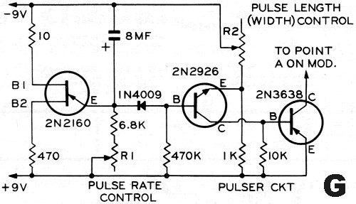
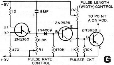
to see how they are used. In illustration G we see a unijunction
transistor, per E above. An odd fact with such transistors is that
in many cases B1 and B2 can be switched, with little or no change
in operation. But better connect them as indicated, where B1 and
B2 are specified, as is the case here. Following along the circuit
to the right (circuits are usually drawn in a logical sequence,
with the parts that initiate action at left, and parts that act
later strung out to the right - though this is not always observed),
the 2N2160 pulse oscillator feeds into the transistor to its right,
via a diode.
Connected to the two are the resistors that feed current to the
various elements, and the variable resistors that change operation
to give the required shift in pulse rate and length. The 2N3638
at the right-hand end of the circuit is an amplifier, which also
isolates the pulser components from further circuitry in the transmitter
which might cause unwanted pulse variations. Often a circuit designer
will place actual values on most of the components, as is the case
here, but a few are designated by a specific R or C number - R1
and R2 in this case.
This means that there might be something special about these
parts which is further explained in the text, as is the case here.
For ease in referring to transistors, they are often given "Q" numbers
in a circuit; the 2N2160 would be Q1, the 2N2926 would be Q2 and
so on. "Q" has no special meaning; it's just a designation generally
meaning transistor - the same as V stands for any vacuum tube, in
a circuit utilizing these components.
Tube sockets are seldom indicated in a circuit, the leads going
right to the tube elements. The same is true of transistor sockets.
Actually, the vast majority of transistors are used without sockets,
which is not true of tubes (except for the sub-miniature types).
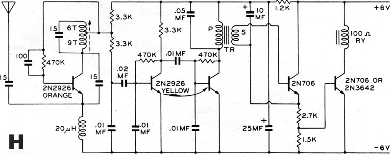
 For
a more complex circuit we see strung together (H) a collection of
the circuit elements we have covered in the past three issues of
this series. And again, the action starts at the far left, with
an antenna to pick up a signal, followed by the orange 2N2926 (due
to wide variations in characteristics, some transistors are not
only marked with a nominal type designation, but are color-coded
by actual test after manufacture, to tie individual characteristics
down more tightly, as is the case here). We see several different
styles of coils - more elegantly referred to as "inductances." One
appears above the orange transistor, and those who read Part 9 carefully
will realize that the dotted line vertically alongside the coil
means it has a powdered iron core, and the arrow on this line indicates
it is adjustable. This is where you tune the receiver to the desired
incoming signal. For
a more complex circuit we see strung together (H) a collection of
the circuit elements we have covered in the past three issues of
this series. And again, the action starts at the far left, with
an antenna to pick up a signal, followed by the orange 2N2926 (due
to wide variations in characteristics, some transistors are not
only marked with a nominal type designation, but are color-coded
by actual test after manufacture, to tie individual characteristics
down more tightly, as is the case here). We see several different
styles of coils - more elegantly referred to as "inductances." One
appears above the orange transistor, and those who read Part 9 carefully
will realize that the dotted line vertically alongside the coil
means it has a powdered iron core, and the arrow on this line indicates
it is adjustable. This is where you tune the receiver to the desired
incoming signal.
Two amplifier transistors come next (the "yellow" units) with the
signal then going through a transformer (TR) and on to two more
transistors. The last one to the right feeds power to the "load"
- in this case a relay of 100 ohms winding resistance. And again,
resistors lead to various transistor elements, as required for their
particular performances. Since this is a radio frequency circuit,
and also has audio frequencies at various points, several circuit
parts have capacitors running to ground, in this case the battery
minus lead.
As the reader will see from the last three parts, circuits aren't
really so fearsome. You don't have to know how each part operates
(though it's helpful) to get a general idea of how the parts are
connected. And a little general info, as we have given in the last
three parts of this series, can be most useful to the average R/Cer,
who really couldn't care less what goes in inside his equipment.
We would like to suggest that readers of this material write
us with suggestions for future parts, criticisms, comments, etc.
This whole series was really launched on the basis of a few letters
from beginning R/Cers. We hope to keep the contents at a level which
will really aid such R/Cers.
Posted October 25, 2014
|