|
This propeller extension shaft
featured in a 1941 issue of Flying Aces magazine
is an example of a concept that seemed like a good idea on paper, but probably proved
to be a disaster in practice. If you have ever had an R/C helicopter with an even
slightly bent main rotor shaft, then you know how the situation causes vibrations
whose severity varies with the amount of bending and the rotation rate of the shaft.
Helicopter main rotors turn at a fairly low rate compared to an aircraft propeller,
although the mass and diameter of the propeller is much less than a rotor. Even
so, I imagine the vibration caused by even a slightly bent propeller shaft extension
when the engine is running at peak RPM is very high - enough to cause the situation
to quickly get worse. It is a runaway situation where the bend increases, causing
worse vibration, which causes more bending, causing greater vibration, etc., etc.,
etc. An additional problem would be caused by the longer moment arm causing additional
wear on the crankshaft bearings and/or bushings, particularly during abrupt change
in the airplane's pitch angle. The proof that propeller extension shafts were not
- at least in the couple hundred vintage model airplane magazines I own - advertised
for sale by either OEM's (original equipment manufacturers) or by distributors.
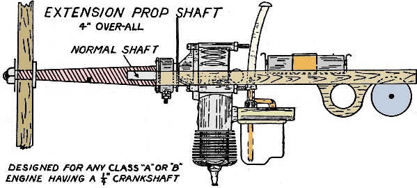
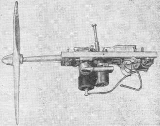
"New Extension Shaft Reduces Engine Repairs
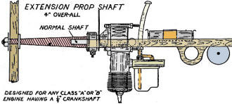
Extension prop shaft. Designed for and Class "A" or "B" engine
having a 1/4" crankshaft.
By Joe Roth
A practical idea to increase flying efficiency, offers new gas design possibilities.
One of the latest contributions to the sport of gas model flying is the practical
use of an extended propeller shaft. This newly designed feature offers the model
builder, within reasonable limits, opportunities to "go to town" in working out
some super-stream-lined design.
The actual length of the shaft measures four inches overall. It was originally
intended to fashion the shaft out of dural but due to government priorities the
use of this alloy is being meted out very carefully to plants working on defense
contracts and so the model industry must wait. Machined from rolled steel, the shaft
weighs 1 3/4 ounces.
It has been designed to fit securely to the shaft of any Class" A" or "B" engine
having a 1/4" diameter.
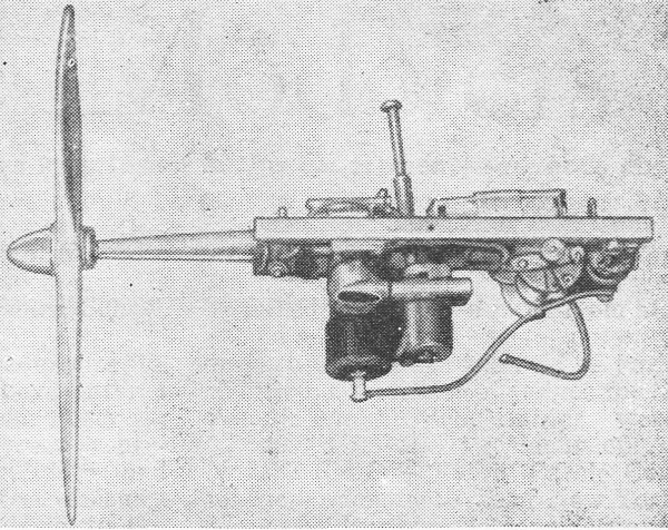
The method of attaching an extension shaft to these types of gas engines is simple.
First the propnut and washer are removed. Then a lock washer is placed firmly against
the driving washer of the engine. The extension shaft is screwed securely against
the lock washer and tightened until the lock washer is closed. To obtain better
security, it is suggested that an additional twist with a monkey wrench is given.
The extension shaft is used to best advantage on inverted engines.
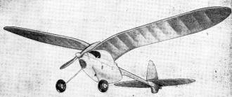
Wider latitude is allowed for fuselage design through the use
of a longer shaft. C/L and C/G are brought ideally closer.
Next, a large fibre washer is placed against the shaft collar followed by the
replacement of the propeller itself. The prop washer is then installed and tightened
in position by the shaft nut. In some cases, depending upon what engine is used
to attach the extension shaft, it is necessary to remove the first few threads with
a drill or reamer so that the lock washer will close properly.
The addition of the extended shaft acts as a small flywheel thus increasing the
revolutions per minute to an appreciable extent.
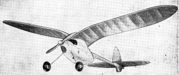
Getting back to the advantage offered to produce some "extra originality" in
your ship, the following practical uses are given: With the use of the longer shaft,
the engine may be placed farther back in the fuselage as is possible thereby keeping
the weight close to the center of gravity. Better balancing and trimming is the
result.
By being placed well back in the fuselage, the motor is offered ample protection
in the event of a serious crack-up. The steel shaft is thoroughly seasoned to withstand
hardest impacts. Keeping the engine clean from dirt and grit constantly being blown
around the field is another advantage offered by the extended shaft.
In attempting to duplicate scale models, the use of the elongated shaft permits
the design of the model plane's cowl to be accurately reproduced regardless of its
shape.
The matter of cooling the enclosed engine is taken care of by the simple process
of cutting out a sufficient area in front of the nose cowl and facing it with a
piece of metal window screening. A modernistic design in the form of grill work
can be added to point up the appearance of the ship.
As shown in the sketch, the most practical method of employing the extension
shaft is to invert the engine. This also necessitates the use of a longer or flexible
needle valve.
Posted September 9, 2023
|