|
At the time this "Dual Rotation-Reverse Thrust Propeller"
article
appeared in Flying Age magazine in 1945, the jet-engine-powered
aircraft were still mostly in the developmental stage, although both Axis and
Allied countries had managed to deploy a design or two at the tail end of World
War II. Commercial and military aircraft had been using variable pitch
propellers for a long time, even with reverse pitch for aerodynamic braking. The
concept of coaxial, counter-rotating propellers was a relatively new idea in
terms of building and testing working models for full-scale aircraft. Four
primary advantages of the configuration were more thrust for a given projected
propeller area, and the reduction or even total elimination of the
counter-torque associated with a normal propeller, the reduction or total
elimination of gyroscopic precession, and the reduction or total elimination
of p−factor (asymmetric
thrust produced by propeller blades presenting unequal angles of attack to the
relative wind). History shows that while the counter-rotating propeller has been
employed successfully in certain instances, it has not enjoyed widespread
acceptance - primarily due to cost and complexity.
Dual Rotation-Reverse Thrust Propeller
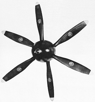
Curtiss dual-rotation prop, a twin, three-bladed. It will be used where diameters
are too large for single rotation efficiency.
Biggest news in props are these new developments, now being perfected and soon
to be more than high experiments.
The real "hot stuff" in propeller news is dual rotation. It was absolutely called
for. As engine horsepower and altitude ratings increased, the propeller had to go
right along. The early propellers, as we have seen, were two-bladed with narrow
blades. They were progressively superseded by three-bladed props with blades of
increasingly wider width and then by four-bladed propellers which in turn were forced
to employ wider and wider blades. To go beyond that point really efficiently, it
was necessary to consider dual rotation very very seriously.
The principle of dual, or counter, rotation is not new. The first recorded flight
of such an arrangement, but without controllable propellers, was that of Wolf Hirth
in February, 1912, near Berlin, in a Loutzkoy monoplane with two 100-hp. Argus engines,
each separately driving a tractor propeller. Its first modern successful use was
in the Italian Macchi-Castoldi twin-float racing seaplane which established a world
record of 440 m.p.h. in 1934. The multiple engines of this plane drove co-axial
counter-rotating shafts on which were mounted fixed-pitch propellers. And later,
in 1938, preliminary tests were conducted at Wright Field on a pursuit plane with
fixed-pitch dual-rotation propellers.
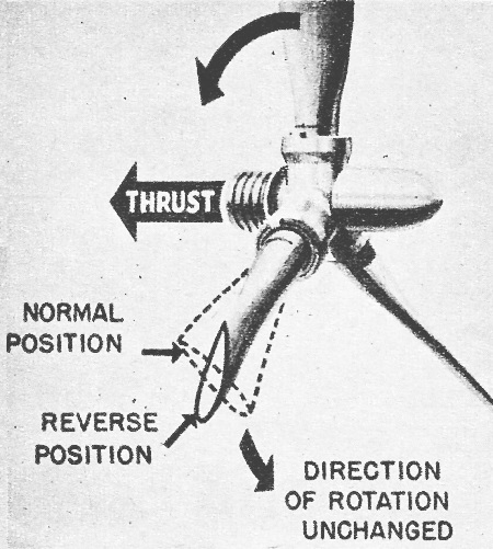
Sketch shows blade pitch change in reverse thrust. Braking is done by changing
the angle to negative pitch while rotating.
Today's dual-rotation props usually consist of two three-blade counter-rotating
propellers mounted in line on concentric propeller shafts. Its great advantages
stem, first, from the fact that the prop in back straightens the slip-stream. Secondly,
the balancing action of the two propellers mounted in line results in almost complete
cancellation of torque reaction. The result of all this is that vying span can be
reduced and so can the ailerons and other control surfaces.
(The torque reaction which is so important has been cancelled by other novel
devices. One of these is on the P-38, where one propeller rotates to the right and
the other to the left. And, incidentally, the greater problem of torque on helicopters
has been partially solved - notably in the small Hiller model - by using dual-rotation
rotors.)
The true application of dual-rotation propellers is primarily on the small, high-speed,
high altitude and highly-powered type of aircraft. Up to the present, however, the
arrangement has been tried primarily on installations where the four-blade, single-rotation
prop was nearly as efficient and of considerably less weight and complication.
To take one example, the Curtiss dual-rotation propeller is electrically actuated
and controlled to give constant speed or fixed-pitch control at all normal conditions
with provisions for full-feathering both propellers simultaneously. Both propellers
operate at the same r.p.m. in opposite directions. In line with present standards,
the outboard propeller rotates toward the right and the inboard propeller toward
the left, when viewed from the rear on a tractor installation. On pusher, installations,
the forward or inboard propeller has right-hand rotation and the rearward or outboard
propeller has left-hand rotation.
Against its important advantages, however, a special reduction gear in the engine
is necessary to provide the counter-rotation feature. That, of course, results in
a weight increase - but it seems to be a price worth paying when improved performance
is considered.
Second of the truly major and most recent propeller developments is that of "reverse
thrust" or aerodynamic braking. The term "reversing" means the operation of rotating
the propeller blades below their positive blade angle until a negative blade angle
is obtained in order to produce a thrust acting in the opposite direction to the
forward thrust normally furnished by the propeller.
What it means is that the airplane can back up. Actually, reverse thrust applies
only to the largest aircraft. Multi-engine flying boats which must land in restricted
areas, and large land transports, trying to reduce excessive landing runs need such
a mechanism. Propellers in reverse pitch have been used on large flying boats for
help in maneuvering on water for a number of years.
For satisfactory operation as a braking propeller, it is necessary that the
pitch range of the blades be substantially increased in order to permit propellers
to rotate to the negative angle of ten to fifteen degrees normally required. With
these angles the propeller will absorb the full rated engine horsepower at rated r.p.m, It is also necessary to have a higher rate of pitch change in going from
the operating angle to the reverse pitch angle than is desirable in the normal operating
pitch range where accurate engine speed control is required. This requirement of
a high rate of pitch change is similar to that used for feathering.
Aerodynamic braking by means of reverse thrust is a simple operation, really.
As the aircraft come in contact with the ground, the reversing circuit is energized
by a cockpit switch so that the propeller blades instantly rotate in the hub from
the positive into the negative blade angle. The direction of propeller rotation,
of course, remains unchanged. The aerodynamic forces produced by the revolving propeller
blades in their positive angle range to pull the airplane forward, now have the
opposite effect in the negative angle range and tend to push the airplane backward.
From a passenger's viewpoint, reverse-thrust braking is a significant development
in aviation. Its cushioning action eliminates any unpleasant wheel-braking effects,
thereby increasing comfort by a tidy bit. It has other ramifications, too, For,
with the adoption of reverse-pitch braking on airplanes, the landing run becomes
shorter than the distance required for take-off, making the take-off distance the
prime basis on which airport lengths will be determined. With the development in
the future of blind landing control, the added feature of reduced landing distances
through use of reverse-pitch propellers should play quite an exceedingly important
part.
Posted June 17, 2023
|