|
There is an old adage about aircraft that says
with enough power just about anything can be made to fly. The F-4 Phantom and F-104 Starfighter
jets are prime examples. In 1957, kids and adults were still obsessed with
flying machines and created
all sorts of crazy craft. Flying dog houses,
witches on brooms, flying doors,
flying lawnmowers, and flying
outhouses were popular novelty projects. Ken Willard even created a
Flying
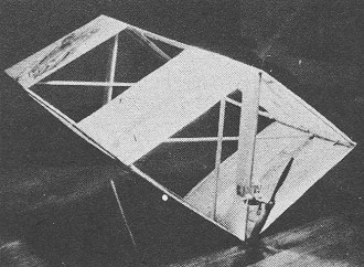
Bandana. This Cox .049-powered box kite doesn't fall into the same category as an
F-4 Phantom, but it does apply as far as making anything fly if you hang an engine on
it. Although author McLarty claims you can adapt a toy store box kite, he also includes
plans for building from scratch.
Flite Kite .049-Powered Box Kite
By J. Lowrie McLarty
 Box kites have been used for centuries by the
Chinese as a national pastime; however, even their best kites could not fly without benefit
of some wind. Flite Kite not only flies without wind but without string as well. Any
box kite can be adapted to fly using the steps below. The kite described is the 25-cent
kind sold in local dime and hobby stores with about a 28 inch length. Some balsa, paper,
cement and a Half-A engine complete the bill of material and an hour or less should see
your Flite Kite ready to go. Box kites have been used for centuries by the
Chinese as a national pastime; however, even their best kites could not fly without benefit
of some wind. Flite Kite not only flies without wind but without string as well. Any
box kite can be adapted to fly using the steps below. The kite described is the 25-cent
kind sold in local dime and hobby stores with about a 28 inch length. Some balsa, paper,
cement and a Half-A engine complete the bill of material and an hour or less should see
your Flite Kite ready to go.
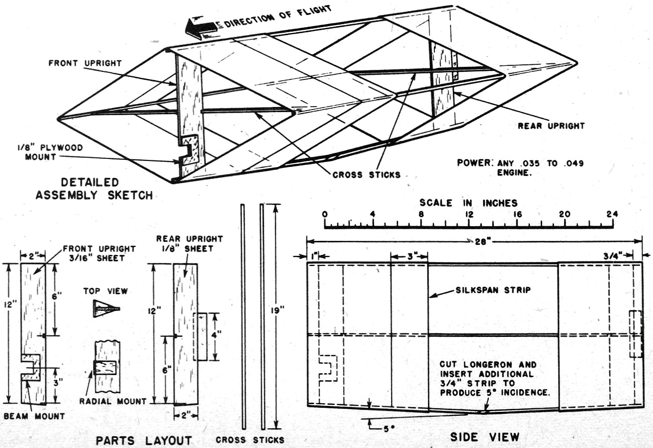
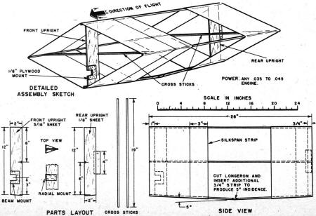
The construction and assembly steps are as follows: Step 1) From 3/16 x 2 hard balsa
sheet cut the front upright with a notch for the cross stick shown in step 3 and either
make a cut out if your engine is beam mounted or cement on balsa angle blocks if the
engine is firewall or radial mounted. In either case use 1/8 ply between engine and balsa
and cement all pieces well.
Step 2) From 1/8 x 2 balsa sheet cut the rear upright and notch to fit the cross stick
shown in step 3. Cement and pin a thin aluminum or fibre 1" x 4" piece as a rudder.
Step 3) From 3/16 x 3/8 hard balsa cut two cross sticks to be trimmed to exact length
on assembly step 4.
Step 4) Assemble kite as per box kite assembly instructions except use uprights and
cross sticks made in steps 1, 2, and 3. Cross sticks step 3 are to be as long as possible
to make the covering tight. Wind and cement thread 3 inches behind front box kite panels
and cover entirely around with Silkspan folded over and cemented in a manner similar
to the box kite panels. Cut the bottom longeron, insert a piece made from the discarded
box kite cross sticks to make the longeron 3/4 inch longer than it was and bind with
thread and cement.
 This operation provides incidence between front and
rear panels to give longitudinal stability. This operation provides incidence between front and
rear panels to give longitudinal stability.
Step 5) Entire model should be given 2 or more coats of plain dope and another of
fuel proofer if a glow engine is used instead of a diesel. Mount the engine and balance
the model at the rear of the front panels as shown in step 4. Use bolts as weights cemented
at the front or the rear to obtain this C. G. position. The final C. G. will be determined
by the glide which should be flat without a tendency to dive, climb or go through a series
of stalls. The weight should be shifted for adjustment. Some down thrust may be necessary
with higher powered engines.
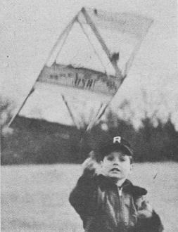
Tethered flights can be made overhead with the usual box kite harness but with the
string arrangement installed upside down as if the tail of the plane were the front of
the kite.
Flite Kite Plans
Posted February 3, 2018
|